
How brass alloy choice affects industrial machining part tolerances
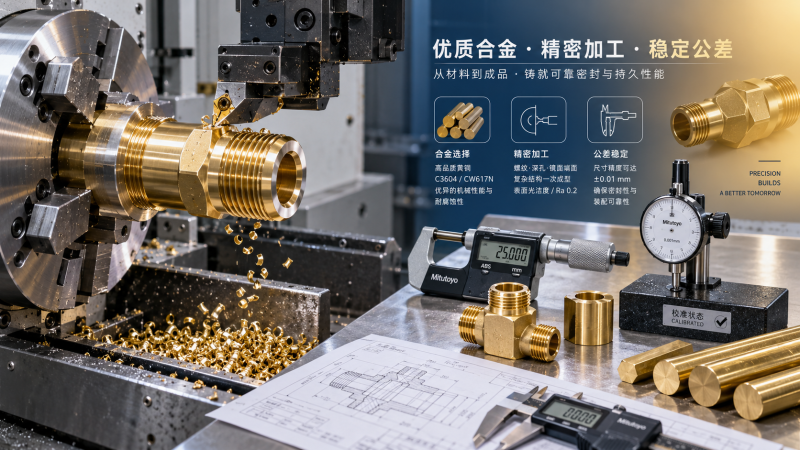
How Brass Alloy Choice Affects Tolerances in Industrial Machining Brass Parts
For technical evaluators, brass alloy selection is not a purchasing detail to settle after the drawing is released. It is a primary control point for achieving reliable tolerances in industrial machining brass parts. Two components may share the same nominal dimensions, CNC program, and inspection plan, yet produce markedly different results when the material changes from a free-machining brass to a low-lead or high-zinc grade.
The reason is straightforward, although the consequences are often underestimated: brass is a family of copper-zinc alloys rather than one uniform material. Lead content, zinc ratio, microstructure, hardness, chip behavior, residual stress, and thermal response all influence how a part reacts under cutting forces. Those variables affect tool wear, bore size stability, thread quality, surface finish, and the ability to hold tolerances across a production run.
When a drawing calls for a critical sealing diameter, a concentric threaded port, or a close-fit sliding feature, the practical question is not simply “Can this alloy be machined?” Nearly all common brass grades can. The more useful question is: Can this grade be machined repeatedly, within the required tolerance band, using a stable and auditable process?
Tolerance is a system outcome, not a material property alone
A brass grade does not carry a tolerance rating by itself. Final capability emerges from the relationship between the alloy, stock condition, feature geometry, machine rigidity, workholding, cutting tools, coolant strategy, and inspection method. Still, material choice sets the starting conditions for that system.
For example, a free-cutting alloy may generate short, controlled chips and place less load on the cutting edge. This supports stable tool offsets and predictable dimensions during long runs. A lower-lead alternative may form more continuous chips, increase the tendency for built-up edge, and require different tool geometry or cycle parameters. Neither outcome is inherently unacceptable, but treating both materials as interchangeable can lead to avoidable variation.
Technical reviewers should therefore separate three questions that are sometimes blended together:
- Can the alloy meet the functional requirements for pressure, corrosion exposure, conductivity, or joining?
- Can it achieve the specified dimensional and geometric tolerances in prototype production?
- Can it sustain those results through normal production variation, tool changes, lot changes, and inspection intervals?
The third question is where alloy selection has its greatest commercial and operational impact.
Why common brass grades behave differently on the machine
Brass generally offers favorable machinability compared with many steels, stainless steels, and aluminum alloys. However, the differences among brass families are material to tolerance-critical work. Copper content tends to support ductility and corrosion resistance; higher zinc levels alter strength and phase structure; lead historically improves chip breakage and lubricity at the cutting zone. Modern regulatory requirements have also increased the use of low-lead and lead-free alternatives, making process validation more important than it was for traditional free-machining grades.
The table is a starting point, not a replacement for trial machining. Chemical limits, temper, product form, supplier practice, and applicable standards all affect actual behavior. A C36000 bar and a low-lead substitute, for instance, should not be scheduled with identical process assumptions merely because both are described as “machinable brass.”
Lead content and chip control: the practical connection
In traditional free-machining brass, dispersed lead supports chip segmentation and helps reduce friction at the tool-workpiece interface. The result is usually clean chip evacuation, lower risk of material smearing, and less tendency for the cut to drift as tools age. For high-volume screw-machined fittings, terminals, valve components, and threaded inserts, this is one reason free-machining brass remains a familiar benchmark.
Where lead-free or low-lead compliance is required, the machining process often becomes less forgiving. The material may be more prone to stringy chips, burrs around cross-holes, or built-up edge on drills and finishing tools. These conditions can affect a seemingly simple tolerance: a drilled bore may measure correctly at first-piece inspection but show gradual variation as the edge condition changes.
That does not mean low-lead brass cannot support precision work. It means the control plan should be built around its actual cutting behavior. Tool suppliers may recommend different carbide grades, sharper rake geometries, modified chip-breaker forms, or changes to coolant delivery. Cycle-time targets should be reviewed alongside dimensional capability; pushing a low-lead alloy at a speed proven for C36000 can create instability that inspection must then chase.
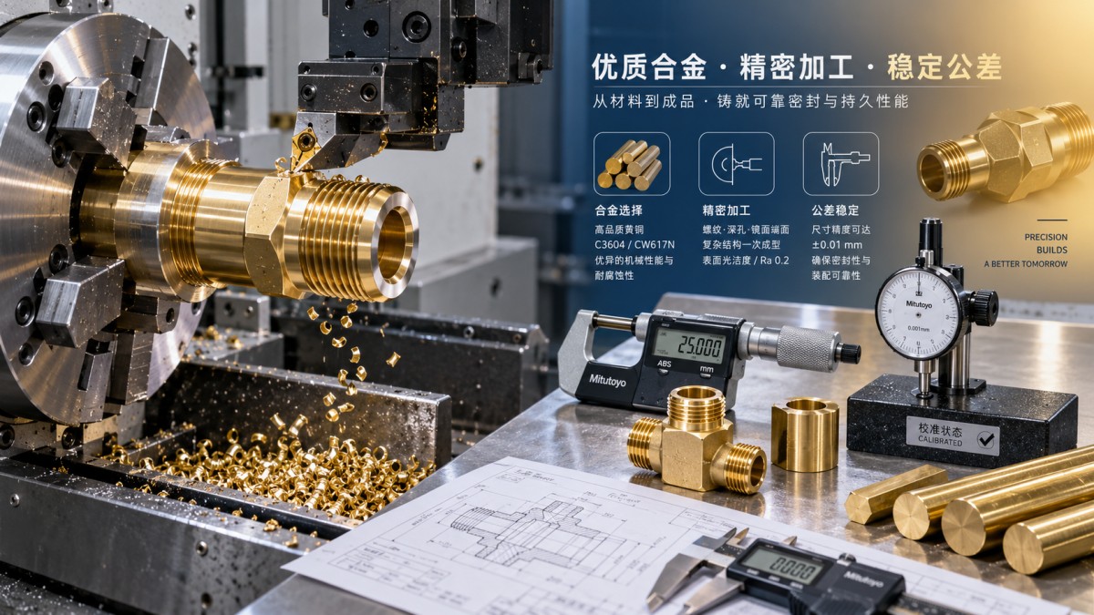
Where alloy choice most often appears in the inspection data
Material-driven variation is rarely distributed evenly across the part. It tends to show up in features where the cutting process is sensitive to heat, edge loading, chip packing, or elastic movement.
Small drilled holes and deep bores
Drilling is often the first place where a changed brass alloy reveals itself. Chip evacuation becomes increasingly important as depth-to-diameter ratio rises. Poorly broken chips can score the bore, interfere with coolant access, raise torque, and accelerate drill wear. The dimensional symptom may be an oversized hole, taper, loss of cylindricity, or a surface condition that compromises a seal even though diameter remains within limits.
For a tight bore, evaluators should ask how size is produced and verified. A drilled-only feature, reamed bore, interpolated bore, and honed bore each respond differently to a change in alloy. The final process must be aligned with the tolerance and function, not just the nominal dimension on the drawing.
Threads and sealing interfaces
Brass is commonly selected for fluid-control components, electrical hardware, connectors, and fasteners because it combines corrosion resistance with workable machining characteristics. In these applications, thread form and sealing geometry often matter more than an isolated diameter callout.
A softer, more ductile brass can leave burrs at thread runouts or deform slightly if workholding is aggressive. A harder or less free-cutting grade may reduce the comfort margin for taps, forming tools, and thread-turning inserts. Pitch diameter, flank finish, concentricity to a sealing face, and burr removal all deserve attention. A thread gauge alone may not reveal whether a component will assemble smoothly after plating, coating, or repeated service cycles.
Thin walls, long shafts, and asymmetric geometries
Stress distribution in raw material becomes relevant when machining removes material unevenly. Although brass is often considered dimensionally stable, certain forms and tempers can still distort when thin sections, flats, slots, or eccentric features are introduced. This is especially important for valve sleeves, precision housings, sensor bodies, and components with interrupted cuts.
The appropriate response is not automatically to specify a more expensive alloy. Better results may come from a revised machining sequence, intermediate stress-relief consideration where suitable, softer jaws, reduced clamping force, or leaving and removing finish stock in controlled stages. Material selection and process planning should be reviewed together.
Thermal behavior matters even when brass cuts easily
Brass conducts heat relatively well, but heat still affects dimensional control. During machining, the workpiece, tool, fixture, and machine structure do not warm at the same rate. On a short production cycle this may be negligible; on a run involving close diameters, multiple operations, or a heated shop environment, it can influence measured results.
Thermal expansion is particularly relevant when tolerances are narrow relative to part size. A component measured immediately after machining may not match its stabilized room-temperature condition. This does not make brass unusual; it simply reinforces the need for measurement discipline. Inspection instructions should define the reference temperature or stabilization practice when the tolerance warrants it.
Alloy changes can modify cutting force and the heat entering the part. If a new low-lead alloy requires more cutting energy, a process that previously held a critical outside diameter comfortably may need compensation or a revised inspection frequency. Treating the first approved sample as proof of long-run thermal stability is a common mistake.
A practical material-selection framework for technical evaluators
Before finalizing a brass specification, it is helpful to review the part through a small number of decision gates. This avoids the familiar situation in which functional material approval is granted early, while manufacturing learns later that the tolerance stack is far less robust than expected.
- Identify the critical-to-function features. Mark sealing lands, press fits, bearing surfaces, precision bores, thread interfaces, electrical contact areas, and datum relationships. Not every dimension needs the same process capability.
- State the material requirement clearly. Specify the recognized alloy designation, applicable standard, product form, temper where relevant, and any regulatory restriction on lead or other elements. “Brass” is not enough for a tolerance-critical quotation.
- Connect tolerance bands to manufacturing routes. Ask whether the feature will be turned, milled, drilled, reamed, broached, thread-formed, thread-cut, or finished in a secondary operation. The selected alloy should be evaluated against that route.
- Review stock quality and traceability. Diameter consistency, straightness, surface condition, chemistry certification, and batch traceability influence repeatability before the first cutting tool touches the part.
- Validate with representative production conditions. A prototype made slowly by an experienced operator is useful, but it is not a production capability study. Validation should reflect intended machines, tooling, workholding, inspection equipment, and realistic tool-life progression.
- Define response rules for material-lot variation. A mature control plan identifies what triggers offset adjustments, additional inspection, tool replacement, or engineering review when a new lot behaves differently.
Standards, drawings, and the risk of ambiguous substitution
In global sourcing, alloy names can be misleading. Regional designations under ASTM, EN, JIS, DIN, or national systems may appear similar while chemical ranges, mechanical requirements, and intended product forms differ. An alloy “equivalent” for general use may not be equivalent for a part whose capability depends on chip formation or hardness range.
For industrial machining brass parts, the drawing or procurement package should ideally identify the material standard and grade, then distinguish between permitted alternatives and unapproved substitutions. If a lead-free alternative is acceptable, it should be listed with its own validation expectations rather than implied as a universal replacement.
This detail is valuable for procurement teams as well as engineers. It reduces disputes caused by receiving a chemically compliant material that performs differently in machining, plating, brazing, or assembly. It also creates a clearer audit trail when a tolerance issue must be traced to material, tooling, programming, or inspection conditions.
What not to assume when reviewing a brass-machined component
Three assumptions create recurring problems. The first is that higher machinability automatically means higher precision. It often supports repeatability, but machine capability, fixturing, and measurement discipline still set the outcome. The second is that a material substitution affects only cycle time. In reality, it can shift burr behavior, hole quality, tool-change intervals, and geometric consistency. The third is that meeting nominal chemistry guarantees identical machining behavior. Bar condition and microstructural variation can still matter.
The strongest engineering decisions acknowledge these interactions early. They do not reject alternative alloys out of habit, nor do they approve substitutions based only on a material data sheet. Instead, they match functional needs, regulatory requirements, and real machining evidence.
Closing perspective
Choosing brass for a precision component is often sensible because the material family offers corrosion resistance, conductivity, formability, and efficient machinability. Yet the specific grade determines how much process margin is available when tolerances become demanding.
For technical evaluators, the most reliable approach is to regard alloy selection as part of the tolerance strategy. Free-machining brass may offer a stable path for high-volume precision features where regulations permit it. Low-lead, corrosion-resistant, or higher-strength grades may be the better functional choice, provided tooling, workholding, inspection, and qualification are adjusted to suit. When that alignment is established, industrial machining brass parts are more likely to remain consistent not only on the first article, but throughout the production life of the program.
Recommended News
 How ATC tool change time data reveals hidden cycle-time lossesATC tool change time data reveals hidden cycle-time losses, separates mechanical delays from program motion, and helps manufacturers improve uptime, capacity, and delivery confidence.
 What to verify before selecting a sinker EDM machine supplierChoose a reliable sinker EDM machine supplier with confidence. Verify machining trials, electrode compatibility, automation, service support, and total ownership risk.
 How brass alloy choice affects industrial machining part tolerancesIndustrial machining brass parts: discover how alloy selection influences tolerance stability, tool wear, bore accuracy, threads, and reliable high-volume production.
 What to verify before selecting an electronics contract manufacturerElectronics manufacturing solutions: learn what to verify before choosing a contract manufacturing partner, from quality systems and testing to sourcing, traceability, and change control.
 How to check color accuracy before approving custom enamel pinsCustom enamel pins color accuracy starts before approval. Learn how to review Pantone references, proofs, plating, and samples for confident results.
 When do multilayer carbide coatings extend tool life in dry machining?Multilayer carbide coatings extend tool life in dry machining when heat, adhesion, abrasion, and edge loading are controlled. Learn how to match layers, substrates, and parameters for reliable performance.
 When occupancy controls reduce warehouse lighting energy wasteWarehouse lighting occupancy controls cut energy waste through smarter zoning, sensor placement, dimming, and commissioning. Discover practical strategies for safer, lower-cost operations.
 How to size an ESS for reducing peak-demand chargesESS sizing for peak-demand charge reduction: learn how to match power, usable energy, tariff rules, controls, and recharge strategy to lower billed demand reliably.
 How textile chemicals affect dye-house wastewater treatment costsTextile chemicals can raise dye-house wastewater treatment costs through COD, color, sludge, salt, and fouling. Discover practical ways to assess total chemical cost.
 When does 5-axis machining make sense for furniture manufacturing?Furniture manufacturing leaders: discover when 5-axis machining delivers real value through complex geometry, fewer setups, better joinery, and premium finishes.
 How to read a 5-axis positioning accuracy chart before machine acceptance5 axis positioning accuracy chart guide for machine acceptance: learn to assess error, repeatability, backlash, and rotary-axis risks before production sign-off.
 When do sludge dewatering machines lower hauling costs?Sludge dewatering machines cut hauling costs when higher cake solids reduce loads, weight, and collection frequency. Explore thresholds, savings, and selection factors.
 How to verify CE certification for industrial pumps before installationIndustrial pumps CE certified? Learn how to verify declarations, documentation, hazardous-area suitability, and installation compliance before commissioning.
 How to compare a plasma cutting machine supplier before placing an orderCompare a plasma cutting machine supplier with confidence—evaluate cut quality, total cost, consumables, and after-sales support before you order.
 Which factory upgrade projects benefit most from industrial technology solutions?Industrial technology solutions factory upgrade projects deliver the most value when they remove bottlenecks, cut downtime, improve quality, and strengthen resilience. Explore high-impact priorities.
 When a high precision CNC grinding machine justifies its costDiscover when a high precision CNC grinding machine delivers real ROI through repeatable quality, lower scrap, faster verification, and controlled production.
 When do industrial lubricants for compressors need oil analysis?Industrial lubricants for compressors need oil analysis at baseline, under harsh operating conditions, and after warning signs. Learn how testing prevents downtime and protects equipment.
 How CNC controller processing speed affects cycle times in EuropeCNC controller processing speed Europe: discover how look-ahead, interpolation and CAM optimisation can cut cycle times while protecting precision and surface quality.
 What to verify before using supplier sourcing solutions in EuropeSupplier sourcing solutions Europe: verify capabilities, compliance, traceability, total cost, and supply resilience before choosing reliable industrial partners.
 When smart fabrics are reliable enough for industrial wearablesSmart fabrics for industrial wearables: learn how to validate durability, signal quality, cleaning resilience, and safe failure performance before deployment.
 How supply chain management for exporters reduces customs delaysSupply chain management for exporters helps prevent customs delays with accurate data, origin checks, importer readiness, and proactive shipment controls. Explore practical strategies now.

















Search News
Popular Tags