
When does pneumatic clamping suit a machining operation?

A pneumatic clamping system machining setup can be a practical choice when fast, repeatable workholding matters more than maximum clamping force. It is particularly relevant to high-volume operations, automated loading, and applications where regulated air pressure can secure parts without excessive deformation. The decision depends on cutting forces, component geometry, positional accuracy, air supply reliability, and safety requirements. Those factors determine whether pneumatic clamping can deliver a stable process or whether hydraulic or mechanical alternatives are better suited.
Where pneumatic clamping earns its place
Pneumatic workholding is most attractive when a part needs to be loaded, located and released frequently, while the machining forces remain within a range the fixture can control. A regulated air supply operates cylinders or other actuators that move clamps into position. Because actuation can be integrated with a machine or loading system, the operator does not have to tighten every clamp by hand on each cycle.
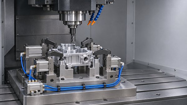
Consider a family of small machined housings produced on a vertical machining center. Each part has usable datum faces, the stock variation is controlled, and the operation consists mainly of drilling, light milling and finishing. A fixture with positive locators and several pneumatic clamps may offer a practical balance: the part can be loaded quickly, the clamps can be sequenced, and pressure can be adjusted to avoid marking a relatively thin wall.
That same fixture may not be suitable for an aggressive roughing pass on an irregular casting. Heavy interrupted cuts, substantial stock variation and uneven contact areas can turn a convenient clamping method into a source of movement. The question is not whether air can close the clamp; it is whether the complete fixture can resist the forces and moments generated throughout the toolpath.
Pneumatics can also make sense in mixed production when fixtures use interchangeable nests or adjustable locators. However, frequent product changes reduce the value of fast actuation if every changeover still requires extensive adjustment and requalification. Fixture change time, not just cylinder response, belongs in the cycle-time calculation.
Start with the load path, not the cylinder catalogue
The most useful early exercise is to trace the cutting load from the tool, through the workpiece and into the fixture base. Identify the direction in which the cutter could push or lift the part. Then identify which fixed supports, locators and clamps resist that movement.
A well-designed fixture generally uses solid locators to establish position and resist predictable lateral loads, rather than relying entirely on friction under the clamps. Clamps hold the workpiece against its locating surfaces; they should not be expected to compensate for poor support or an unfavorable cutting direction.
For a basic cylinder, theoretical force is pressure multiplied by effective piston area. That is only a starting point. Available force at the workpiece can differ because of rod-side area, actuator friction, linkage geometry, clamp leverage, pressure losses and the position of the mechanism during its stroke. A swing clamp, for example, must complete its movement and reach the intended clamping zone before its published output is meaningful.
Use the lowest pressure expected at the fixture during production, not simply the compressor’s nominal setting. Evaluate the most demanding tool engagement, including entry, exit, interrupted cutting and any operation that could create a lifting moment. If the design depends on friction, account for the actual contact materials and the possible presence of coolant or chips. A dry, clean bench test may be a poor representation of a machining enclosure.
Clamping force also needs a margin appropriate to the uncertainty in the load estimate and the consequences of movement. There is no universal multiplier that makes every fixture safe. Where cutting loads are uncertain, a conservative trial with measured or otherwise validated conditions is more useful than treating a calculated value as exact.
Low deformation is possible, but not automatic
The ability to regulate air pressure is valuable for thin sections, near-net-shape castings and components with cosmetic or functional surfaces. It allows the fixture designer to investigate the lowest pressure that still provides adequate retention. It does not guarantee that the part will remain round, flat or dimensionally stable.
A clamp pressing on an unsupported wall can distort a component even at modest force. After machining and release, the wall may spring back and the measured feature may be out of tolerance. Moving the contact point closer to a support, spreading the load through a suitable pad or adding a controlled support beneath the machining zone may help more than reducing pressure alone.
Support design has its own trap: a movable support that pushes the part away from its datum can introduce location error. Establish the primary locating contacts first, then bring auxiliary supports into contact in a controlled way. Check whether the support locks or changes load as the clamp closes.
For a critical bore or sealing face, compare measurements with the component clamped and after release. If practical, also inspect the fixture’s locating surfaces for chip contamination and wear. A repeatable clamping sequence cannot deliver repeatable part position if a chip sits under a datum pad.

Air supply and control details that change the result
A fixture is only as dependable as the air reaching it. Pressure can fall during simultaneous actuator movement, because of undersized lines, long supply runs, clogged filters, leaks or demand elsewhere in the plant. A regulator setting alone does not show what happens at the cylinder when the machine is cycling.
Check pressure at a representative point in the fixture circuit under the intended operating sequence. Air quality matters too: water, oil contamination and particles can affect valves and seals, although the required filtration and lubrication arrangement must follow the component manufacturers’ instructions. Adding oil to a system is not automatically beneficial and may be inappropriate for some components.
Response time deserves attention in automated cells. A long air line or restricted exhaust can delay full clamping even when the valve has switched. Program delays should be based on demonstrated operation under realistic pressure and temperature conditions, not on the assumption that a command equals completed movement.
Position sensing can help establish that a clamp has reached a commanded position, but it does not necessarily prove that the correct part is present or that adequate force is being applied. A pressure switch likewise indicates pressure at its sensing point, not the actual grip on each contact. Depending on the risk assessment, the control scheme may need a combination of part-present detection, clamp-position confirmation and pressure monitoring.
What happens when air pressure is lost?
This question should be answered before selecting valves or writing the machine sequence. An ordinary pneumatic cylinder may not retain a safe clamping force after a supply failure, hose rupture, emergency stop or maintenance isolation. A part that was secure during a normal cycle can become hazardous if the spindle continues to move or if the workpiece is accessible while unsecured.
Possible design measures include mechanically locking clamps, spring-applied mechanisms, retained-pressure arrangements or a separate mechanical restraint. Each has limits. Trapped air, for example, can leak, and a valve arrangement that helps during one failure may not protect against a downstream hose failure. The required response must be determined for the actual circuit and failure modes.
The machine’s stop behavior, guarding, restart logic and the possibility of a tool remaining engaged all matter. Review the fixture with the machine builder and the responsible safety team; confirm applicable requirements against the relevant machinery and safety standards for the installation. A pressure alarm is useful diagnostic information, but it should not be assumed to be a complete safety function.
When another workholding method is the better choice
Hydraulic clamping is often worth evaluating when the available fixture space is tight and the required force is beyond what a practical pneumatic actuator can provide. It can support demanding workholding applications, but introduces its own pump, fluid containment, maintenance and leakage considerations. Hydraulic pressure is not a substitute for good location or a review of pressure-loss behavior.
Mechanical clamps, vises and screw-operated fixtures remain sensible for low-volume work, heavy cuts or applications where simplicity and direct operator control matter more than automated loading. Their trade-off is often longer or more variable handling time, especially where several clamps must be tightened in a defined sequence.
A hybrid arrangement can be the best compromise. Mechanical stops can resist the main cutting direction while pneumatic clamps provide fast downward restraint. Some fixtures use powered clamping for routine loading and a separate mechanical lock where retention during an air failure is required. Such arrangements still need to be checked as a complete system; the presence of a lock does not establish that it is correctly engaged.
Vacuum and magnetic workholding may also be candidates for suitable geometries and materials. Their holding capacity depends heavily on contact conditions and application-specific limits, so they should be compared using the same cutting-load and failure-mode discipline rather than treated as interchangeable with clamps.
A practical trial before committing to the fixture
Before a production release, run representative parts across the expected range of incoming geometry. Include the least favorable support condition, the intended coolant environment and the most demanding cut. Record the pressure at the fixture, inspect contact marks, and check whether critical dimensions change after unclamping. Repeated loading is as important as a single successful cut: it exposes sensitivity to operator placement, chip buildup and clamp sequencing.
The trial should also cover recovery. What happens after an interrupted cycle? Can an operator distinguish a correctly seated part from one caught on a locator? Can a damaged hose or worn clamp pad be replaced without disturbing fixture alignment? Those details affect uptime and serviceability as much as the nominal actuation speed.
A multidisciplinary review, of the kind relevant to G-PME’s work across machining, sealing and fluid-control systems, helps connect fixture performance with air quality, component maintenance and machine integration. The decision should remain grounded in the operation itself: choose pneumatic clamping when the validated load path, deformation control and failure response meet the process requirements, not simply because compressed air is already available.
Recommended News
 CISA Releases Early-November Prices and Indices for Eight Major Steel ProductsCISA steel prices and indices for eight major products offer a market reference for procurement and cost planning. Explore what buyers should verify.
 How to size a CNC surface grinding machine for your workpiecesChoose the right surface cnc grinding machine with practical guidance on travel, clearance, load capacity and accuracy for your workpieces.
 When does pneumatic clamping suit a machining operation?Pneumatic clamping system machining: discover when fast, repeatable workholding makes sense, and how to assess cutting forces, part distortion and safety.
 How application engineering support improves product selectionApplication engineering support improves product selection by aligning specifications with real operating conditions. Discover how to compare options with confidence.
 What affects the price of an industrial air compressor?Understand what affects air compressors price, from capacity and controls to installation and energy costs. Compare quotes and choose the best-value system.
 How mold temperature affects high-precision die castingSee how high precision die casting mold temperature affects tolerances, defects, and tool life—and learn what evidence to request from suppliers.
 How to verify quality standards when selecting mechanical sealsProduct selection guidance for mechanical seals: verify quality standards, material traceability, certifications, and test evidence before you buy.
 Tungsten Prices Rise as Ore Quotes Lead Gains, Adding Pressure on Tool CostsTungsten prices are rising as ore quotes climb, putting pressure on carbide and cutting tool costs. Discover what buyers should watch next.
 How ISO 230-1 addresses machine tool static stiffness testingMachine tool stiffness ISO testing explained: discover how ISO 230-1 guides force-deflection measurements and supports meaningful machine comparisons.
 How to check whether a bulletproof vest is NIJ certifiedLearn how to verify bulletproofvests on the official NIJ Compliant Products List, match labels and configurations, and avoid misleading certification claims.
 How to assess a lubricants supplier's delivery reliabilityAssess a lubricants supplier with practical checks on delivery records, stock availability and contingency plans to reduce supply risks and make confident sourcing decisions.
 Americas Base Oil Weekly: High Crude and Feedstock Costs Compound Supply TightnessAmericas base oil supply is tightening as crude and feedstock costs rise. Explore the impact on Group II+ and Group III availability, pricing and purchasing.
 How to verify organic cotton baby clothes certificationShopping for organiccottonbabyclothes? Learn how to verify GOTS and OCS claims, check certificate details, and choose baby clothing with confidence.
 How corner radius carbide end mills reduce edge chippingDiscover how corner radius carbide end mills reduce edge chipping, improve machining consistency, and support longer tool life with the right geometry and setup.
 How to choose a laser level for outdoor workCompare laserlevels for outdoor work by range, accuracy, durability, and receiver compatibility. Find the right tool for reliable results on site.
 Global Metal-Cutting Semi-Synthetic Coolant Market Forecast to Reach $1.73 Billion by 2030The semi-synthetic metal-cutting coolant market is forecast to reach $1.73 billion by 2030. Explore growth drivers and key considerations for buyers and suppliers.
 How coating thickness affects carbide tool coating costsCarbide coating cost analysis: discover how thickness affects tool prices, wear and cost per part, and learn when a premium coating is worth the investment.
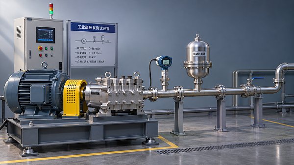
 What pressure stability data should a pump supplier provide?How do I shortlist the right high-pressure pumps supplier for stable pressure? Learn which test data to request and compare bids with confidence.
 How to evaluate an industrial supplier's delivery reliabilityStrengthen industrial procurement support and supplier evaluation with practical checks for delivery records, lead times, capacity, and recovery plans.
 Stonepeak Completes 65% Castrol Acquisition; Former Shell CEO to ChairStonepeak's 65% Castrol acquisition brings new leadership as former Shell CEO Ben van Beurden becomes chair. Explore potential implications for lubricant buyers and suppliers.
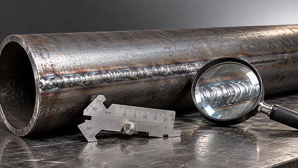
 How to inspect welded iron pipes for seam defectsInspect weldedironpipes for seam defects with a practical guide to visual checks, NDT methods, acceptance criteria, and safe repair decisions.

Search News
Popular Tags