
How to verify tight tolerances in custom machining solutions

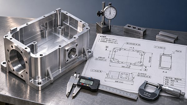
A machined part can pass a quick dimensional check and still fail in assembly. A bore may be the right diameter but incorrectly located; a shaft may measure within its size limits while its surface form prevents a seal from working as intended. Verification therefore starts with the complete drawing requirement and ends with a documented decision supported by an appropriate measurement process.
For tight-tolerance features, a reading inside the specified limits is not always enough to establish conformity. Quality teams also need to know how the feature was measured, whether the equipment and setup were suitable, how much uncertainty surrounds the result, and which acceptance rule applies. The closer a result is to a specification limit, the more consequential those details become.
Start with the requirement the part must actually satisfy
Before choosing a gauge, identify the drawing revision, units, applicable specifications and inspection characteristics. A tolerance is attached to a particular requirement: size, location, orientation, form, profile, surface texture or another defined property. Each may call for a different measurement strategy.
For example, a bore specified as 20.000 mm with a bilateral tolerance of ±0.010 mm has size limits of 19.990 mm and 20.010 mm. A diameter result within those limits addresses the size requirement, but it does not automatically establish the bore’s position relative to mounting faces or demonstrate that its axis meets a separate orientation tolerance.
Geometric dimensioning and tolerancing, or GD&T, adds another layer. Inspectors need to understand the specified datum references, the order in which those references establish the coordinate system, and any modifiers that affect the requirement. A coordinate measuring machine can produce a position result, but that result is only meaningful if the measurement and evaluation follow the drawing’s intended datum scheme and the applicable standard.
Drawings may invoke different standards or editions, including ASME Y14.5 or the ISO geometrical product specification system. Do not assume that similarly named symbols, default rules or evaluation conventions are interchangeable. Where a drawing leaves the interpretation of a critical characteristic unclear, resolve it with engineering before accepting the inspection method or releasing the part.
A useful inspection plan links each significant characteristic to:
- The drawing requirement, revision and applicable specification.
- The feature and datum surfaces used to establish the measurement reference.
- The measurement method, equipment and evaluation procedure.
- The sampling plan and acceptance rule.
- The record that will demonstrate the result and support traceability.
Give particular attention to features that affect fit, sealing, load transfer, alignment or safe operation. A dimension can have a small tolerance without being safety-critical; conversely, a less restrictive feature may have a significant consequence if it fails. Engineering should identify those consequences so that inspection effort follows functional risk.
Choose a measurement method for the feature, not just the tolerance
In custom machining solutions, tight tolerance verification often requires several complementary methods. No single instrument is inherently the best choice for every feature, and a calibration label alone does not establish that a tool is suitable for a particular inspection.
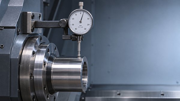
A micrometer may be appropriate for an accessible outside diameter when the measuring faces, contact force and part geometry permit a reliable reading. A calibrated bore gauge can help assess an internal diameter, provided it is set with a suitable reference and used at the required locations and orientations. A height gauge or dedicated fixture may be effective for certain distances when the datum setup is well controlled.
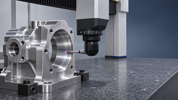
A coordinate measuring machine, or CMM, is useful for complex relationships among features, including many location and orientation requirements. Its value depends on the probing strategy, stylus configuration, datum alignment, number and distribution of points, and software evaluation. A report with several decimal places does not by itself prove that the reported result is accurate to those places.
Form and surface requirements deserve separate consideration. A limited set of CMM points may miss lobing or a local defect on a cylindrical surface. Depending on the requirement, a roundness instrument, contour measuring system or surface texture instrument may be more appropriate. Likewise, optical systems can be useful for small or delicate features, but edge detection, surface finish, lighting and part orientation can influence the result.
For a threaded feature, a functional gauge may establish whether the thread meets the specified gauging criteria, while a separate measurement method may be needed when the drawing or control plan calls for individual thread characteristics. Confirm what a gauge actually verifies before treating its result as evidence for every related requirement.
Choose measurement locations deliberately. A single diameter reading can miss taper, out-of-roundness or a local manufacturing defect. Where those conditions matter, measure at several axial positions and angular orientations, or use a method designed to evaluate the required form. The inspection plan should state the approach clearly enough that another qualified inspector can reproduce it.

Control the setup around the instrument
Part temperature, fixture restraint, cleanliness and handling can change a result. Allow the part, reference standards and equipment to stabilize under the conditions required by the measurement procedure. Temperature matters especially when the tolerance is small relative to the part size or when the part and reference have different thermal expansion characteristics. The conventional reference temperature for geometrical product specifications is 20 °C, but the drawing and applicable standards determine how reference conditions are applied.
Remove chips, coolant residue and burrs where the inspection procedure requires it, without altering the feature being evaluated. Support the part consistently and avoid clamping forces that distort thin walls. For flexible parts, agree on the specified restraint or free-state condition before measurement; otherwise, two careful inspections may produce different answers while each accurately reflects its own setup.
Use uncertainty and a decision rule to judge results near a limit
Every measurement has uncertainty. It can arise from the instrument, calibration references, environment, setup, operator technique, part geometry and the way the measured data are evaluated. The significance of those contributions depends on the feature and method; an uncertainty figure copied from an instrument specification is rarely a complete uncertainty estimate for the finished inspection.
Consider a feature with an upper limit of 20.010 mm. A reported result of 20.009 mm is numerically inside the limit, but it leaves only 0.001 mm of margin. If the measurement uncertainty is large compared with that margin, the reading alone provides limited confidence that the true value lies within specification.
One possible approach is a guard band: the acceptance boundary is set inside the specification limit by an agreed amount. For illustration, if a decision rule uses a 0.002 mm upper guard band, a measured value must be at or below 20.008 mm to meet that acceptance boundary. The value of 0.002 mm is only an example; the appropriate rule depends on the evaluated uncertainty, the risks of false acceptance and false rejection, and contractual or standards requirements.
A result between the acceptance boundary and the specification limit should be handled under the agreed decision rule. It may require further evaluation, a different measurement method or disposition by the responsible authority. Repeatedly measuring until one result passes does not resolve the underlying uncertainty.
ISO 14253-1 addresses decision rules for proving conformity or nonconformity with specifications, taking measurement uncertainty into account. Its application depends on the relevant specification and agreements. Establish the decision rule before inspection, particularly when acceptance decisions have safety, interchangeability or contractual consequences.
Resolution, repeatability and uncertainty are related but distinct. A display increment much smaller than the tolerance can help reveal changes, yet it does not account for systematic error or setup effects. Similarly, a common instrument-to-tolerance ratio can be a useful screening convention if the organization specifies one, but it cannot replace an assessment of the complete measurement process.
Make calibration and inspection records support the decision
Confirm that each instrument is calibrated within its required interval and that calibration is traceable through appropriate references. Review whether the calibration covers the range and conditions relevant to the feature being measured. An instrument can be in calibration and still be unsuitable because its uncertainty, contact geometry or measurement range is inappropriate for the job.
When an external laboratory is used, ISO/IEC 17025 accreditation can provide evidence of competence for activities within its accredited scope. Check the scope against the actual measurement or calibration needed; accreditation does not automatically cover every service the laboratory offers.
For critical features, assess the measurement system under conditions representative of use. Depending on the method, this can include repeated measurements, comparison among operators, checks with reference artifacts and investigation of variation caused by setup. A gauge repeatability and reproducibility study can be useful for suitable measurement systems, but its design and interpretation need to fit the characteristic and production context.
The inspection record should allow someone outside the measurement operation to reconstruct the basis for acceptance. At minimum, retain part and lot identification, drawing revision, characteristics and limits, actual results or applicable gauge outcomes, equipment identification, inspection date and the responsible inspector or system. Record the measurement method, datum setup, sampling plan, uncertainty and decision rule when required by the control plan, contract or applicable standard.
For a safety-relevant feature, preserve the link between the inspection record and the individual part or defined lot. If a result is later challenged, that link makes it possible to identify affected hardware and assess the scope of the issue without treating unrelated material as suspect.
Decide what the inspection says about the batch
A passing first article shows that the inspected part met the requirements covered by that inspection under the stated conditions. It does not, on its own, demonstrate that every subsequent part will conform. Tool wear, fixture changes, material variation and process adjustments can shift results during production.
Set sampling frequency and reaction limits according to the feature’s consequence, process stability, production quantity and agreed quality requirements. For a critical characteristic, the plan may call for more frequent checks, full inspection, process monitoring or a combination of controls. Where destructive testing or measurement time limits the number of samples, make the remaining risk explicit in the control plan.
When a result falls outside the acceptance rule, contain the affected material and investigate both the part and the measurement process. Check the instrument status, reference setup, part identification and procedure before reaching a disposition. If the result is confirmed, assess the interval since the last valid check and identify material that may have been affected. Engineering and the designated quality authority should decide any rework, reinspection or concession in accordance with the applicable requirements.
The strongest verification package connects the drawing, measurement method and acceptance decision closely enough that another qualified person can follow the evidence. For a tight feature, that connection is often more useful than an extra decimal place on the report.
Recommended News
 Which ISO and ASME standards apply to precision part drawings?Which ISO and ASME standards matter for precision part sourcing? Discover key drawing, tolerance and inspection requirements to source with confidence.
 How to compare high-pressure pump suppliers using pressure stability test dataHow do I shortlist the right high-pressure pumps supplier for stable pressure? Compare test data, pressure traces and operating conditions with this practical guide.
 How to verify tight tolerances in custom machining solutionsVerify custom machining solutions tight tolerance requirements with practical guidance on inspection methods, measurement uncertainty and reliable acceptance decisions.
 How to measure spindle nose runout with a dial indicatorMeasure spindle nose run out with a dial indicator. Learn how to set up safely, calculate TIR, and compare results with the right specification.
 How to evaluate 5-axis machining suppliers in North AmericaEvaluate 5 axis machining North America suppliers with confidence. Compare capabilities, quality controls, lead times, and total costs before you commit.
 How do tungsten price changes affect cutting tool costs?Explore tungsten price impact on cutting tool costs, learn how to assess supplier increases, and find smarter ways to control machining costs.
 CISA Releases Early-November Prices and Indices for Eight Major Steel ProductsCISA steel prices and indices for eight major products offer a market reference for procurement and cost planning. Explore what buyers should verify.
 How to size a CNC surface grinding machine for your workpiecesChoose the right surface cnc grinding machine with practical guidance on travel, clearance, load capacity and accuracy for your workpieces.
 When does pneumatic clamping suit a machining operation?Pneumatic clamping system machining: discover when fast, repeatable workholding makes sense, and how to assess cutting forces, part distortion and safety.
 How application engineering support improves product selectionApplication engineering support improves product selection by aligning specifications with real operating conditions. Discover how to compare options with confidence.
 What affects the price of an industrial air compressor?Understand what affects air compressors price, from capacity and controls to installation and energy costs. Compare quotes and choose the best-value system.
 How mold temperature affects high-precision die castingSee how high precision die casting mold temperature affects tolerances, defects, and tool life—and learn what evidence to request from suppliers.
 How to verify quality standards when selecting mechanical sealsProduct selection guidance for mechanical seals: verify quality standards, material traceability, certifications, and test evidence before you buy.
 Tungsten Prices Rise as Ore Quotes Lead Gains, Adding Pressure on Tool CostsTungsten prices are rising as ore quotes climb, putting pressure on carbide and cutting tool costs. Discover what buyers should watch next.
 How ISO 230-1 addresses machine tool static stiffness testingMachine tool stiffness ISO testing explained: discover how ISO 230-1 guides force-deflection measurements and supports meaningful machine comparisons.
 How to check whether a bulletproof vest is NIJ certifiedLearn how to verify bulletproofvests on the official NIJ Compliant Products List, match labels and configurations, and avoid misleading certification claims.
 How to assess a lubricants supplier's delivery reliabilityAssess a lubricants supplier with practical checks on delivery records, stock availability and contingency plans to reduce supply risks and make confident sourcing decisions.
 Americas Base Oil Weekly: High Crude and Feedstock Costs Compound Supply TightnessAmericas base oil supply is tightening as crude and feedstock costs rise. Explore the impact on Group II+ and Group III availability, pricing and purchasing.
 How to verify organic cotton baby clothes certificationShopping for organiccottonbabyclothes? Learn how to verify GOTS and OCS claims, check certificate details, and choose baby clothing with confidence.
 How corner radius carbide end mills reduce edge chippingDiscover how corner radius carbide end mills reduce edge chipping, improve machining consistency, and support longer tool life with the right geometry and setup.
 How to choose a laser level for outdoor workCompare laserlevels for outdoor work by range, accuracy, durability, and receiver compatibility. Find the right tool for reliable results on site.















Search News
Popular Tags