
How predictive maintenance technology detects pump failures early
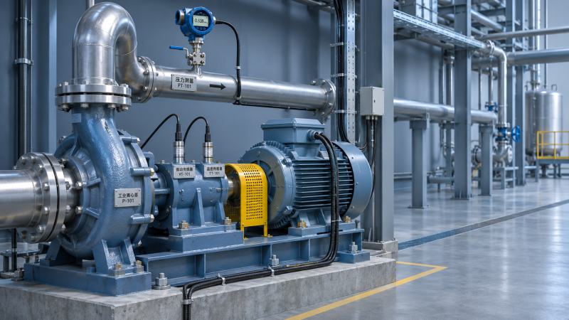
Unexpected pump failures can disrupt production, increase repair costs, and put after-sales maintenance teams under pressure to restore service quickly.
Industrial technology solutions for predictive maintenance help technicians identify early warning signs, such as abnormal vibration, rising temperatures, and changes in pressure or flow, before they develop into costly breakdowns.
By combining sensor data with operating history, maintenance teams can prioritize inspections, plan repairs, and improve equipment uptime. This article explains how these technologies detect emerging pump problems and support more informed maintenance decisions.
The practical answer is that predictive maintenance detects changes associated with developing faults, but technicians must interpret those changes against operating conditions before deciding what action to take.
What Can Predictive Maintenance Detect Before a Pump Fails?
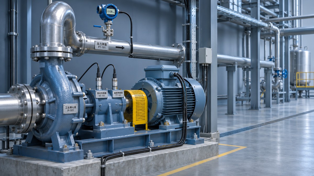
A monitoring system compares current measurements with a pump’s normal behavior, previous measurements, or defined limits. An abnormal pattern can prompt an inspection before performance deteriorates further.
For example, increasing vibration near a bearing may indicate wear, looseness, or misalignment. A simultaneous temperature rise strengthens the case for investigation, but does not confirm the cause.
Technicians can also detect hydraulic problems. Falling flow, unstable suction pressure, and changing vibration may point toward a blocked strainer, insufficient suction head, or cavitation.
Early detection depends on the failure mode, sensor placement, sampling frequency, and operating conditions. Some faults develop gradually; others can occur too quickly for monitoring to provide useful warning.
The goal is therefore actionable notice: enough evidence and time to inspect the pump, obtain parts, and schedule an intervention when operating conditions permit.
Which Pump Measurements Give Technicians the Most Useful Warning?
Start with measurements linked to likely failure modes and service consequences. A critical pump may justify continuous monitoring, while periodic measurements may suit a less critical standby unit.
Vibration: bearings, alignment, and hydraulic instability
Vibration sensors measure changes in mechanical motion. Overall vibration trends can reveal deterioration, while frequency analysis can help distinguish rotating components and recurring fault patterns.
Bearing damage, imbalance, looseness, and misalignment can produce different vibration signatures. However, similar symptoms may arise from hydraulic forces or changes in operating speed.
Place sensors consistently on suitable bearing housings, following equipment and sensor guidance. Record measurement direction, mounting method, speed, and operating point so readings remain comparable.
A rising trend deserves attention even before a fixed alarm limit is reached, particularly when the pump operates under comparable load and the change persists.
Temperature: friction, lubrication, and cooling problems
Bearing and motor temperatures can rise when lubrication deteriorates, cooling is restricted, or friction increases. Seal-area temperature may also provide useful context where measurement is practical.
Compare readings with ambient and process temperatures. A hot bearing alone does not establish a fault if the surrounding conditions or pumped fluid temperature have also changed.
Check lubricant condition, quantity, and specification alongside temperature trends. Excess lubricant, insufficient lubricant, contamination, and blocked cooling passages can all contribute to overheating.
Pressure and flow: changes in hydraulic performance
Suction pressure, discharge pressure, and flow show whether the pump is operating as expected. Together, they can reveal restrictions, recirculation, leakage, or changes in system demand.
Compare readings at the same speed and operating point where possible. A lower flow rate may reflect a valve adjustment or process change rather than pump degradation.
For centrifugal pumps, compare measured differential pressure and flow with the applicable pump curve, accounting for fluid properties, instrument accuracy, and any speed changes.
Electrical and seal indicators: additional context
Motor current, power, and electrical measurements can indicate changing load or motor problems. Their interpretation depends on motor characteristics, drive settings, and the pump’s operating curve.
Seal leakage, seal flush pressure, and barrier-system condition can provide earlier evidence of seal trouble. Monitor these variables where the seal arrangement and fluid make measurement useful.
How Does the System Turn Sensor Readings Into a Maintenance Alert?
The process starts with a trustworthy baseline. Capture data during stable operation across the normal range of speeds, flows, temperatures, and process conditions.
Record the pump model, operating hours, sensor locations, recent repairs, and known defects. Without this context, the system may treat a normal operating change as an anomaly.
Software then compares new readings with historical trends, configured thresholds, or models of expected behavior. Some systems use machine learning; others rely on rules and established condition-monitoring methods.
An alert might identify a rapid vibration increase, repeated pressure fluctuations, or a combination of rising bearing temperature and abnormal vibration at a stable load.
The most useful alert includes the affected asset, measurement, trend, operating conditions, and time of change. It should direct a technician toward verification and a practical next step.
A prediction of remaining useful life requires validated models and suitable failure data. Treat an estimated date as uncertain, and avoid using it as the sole basis for continued operation.
What Should You Do When a Pump Alert Appears?
First, assess immediate operating and safety conditions using site procedures. If readings indicate an unsafe condition, follow the established shutdown and escalation rules without waiting for further analysis.
Next, verify the signal. Check sensor mounting, communication status, calibration records, and recent maintenance. Compare suspicious readings with a handheld instrument or another independent measurement when possible.
Review the trend before the alert, not just the latest value. Note whether the change was gradual or sudden and whether it coincided with a process adjustment.
Compare speed, flow, suction conditions, and fluid temperature with the baseline. A process change may explain the reading, or it may have exposed an underlying pump problem.
Inspect related evidence before selecting a cause. For a vibration alert, examine bearing temperatures, lubrication history, mounting condition, and alignment records where these checks can be performed safely.
Document the finding and assign an action: continue monitoring, conduct a planned inspection, arrange a controlled shutdown, or escalate for specialist analysis according to site procedures.
After repair, capture readings under comparable operating conditions. Confirm whether the abnormal trend has changed, and record the actual defect and repair in the maintenance system.
How Can You Distinguish Common Pump Problems?
No single reading reliably identifies every fault. Use the following patterns to guide an inspection, then confirm the cause through appropriate measurements and physical examination.
Possible bearing deterioration
Look for a sustained vibration increase, changes in bearing-related frequency patterns, and potentially rising bearing temperature. Check lubrication history and contamination before deciding on replacement.
Confirm findings through further vibration analysis or inspection during a planned stop. Similar symptoms can result from looseness, misalignment, or a damaged sensor mount.
Possible cavitation or suction restriction
Listen for unusual noise and review suction pressure, flow, and vibration trends. Check suction strainers, valve positions, liquid level, and changes in fluid temperature.
Cavitation occurs when local pressure falls sufficiently for vapor cavities to form and collapse. Confirm that available suction conditions meet the pump’s requirements at the actual operating point.
Possible misalignment or mechanical looseness
Changes in vibration near the coupling or bearing housings can justify checking alignment, fasteners, and foundation condition. Thermal growth and pipe strain may affect alignment during operation.
Use suitable alignment and inspection procedures during an authorized stop. Verify the correction after restart because changing one component does not guarantee that every contributing cause has been removed.
Possible internal wear or leakage
At comparable speed and operating conditions, declining flow or differential pressure can indicate wear, internal leakage, or a system issue. Check instruments and valve positions first.
Compare performance with the applicable curve and maintenance history. Inspection may be needed to confirm impeller, wear ring, valve, or other component condition.
Which Pumps Should Be Monitored First?
Prioritize pumps whose failure would create significant production disruption, safety consequences, environmental exposure, or long repair delays. Include availability of a reliable standby unit in the assessment.
Next, consider failure history and detectability. Repeated bearing or seal problems may justify monitoring, particularly when measurable symptoms appear early enough to support an intervention.
A pump with infrequent use, low replacement cost, and straightforward repair may not need permanent sensors. Scheduled inspections or periodic portable measurements may offer sufficient coverage.
For a pilot, select a manageable group with clear ownership, accessible measurement points, and reliable maintenance records. Include different operating conditions if the intended rollout will cover them.
Define success before installation: for example, verified detection of developing faults, fewer unplanned stops, faster diagnosis, or better planning of spare parts and service visits.
What Makes a Predictive Maintenance Solution Practical for After-Sales Teams?
Choose a system that provides usable data in the field. Technicians need clear asset identification, accessible trends, alarm history, and instructions suited to the equipment.
Check sensor compatibility with pump speed, temperature, mounting surfaces, and the site environment. Hazardous areas, washdown, corrosion, and communication coverage may require specific equipment choices.
Ask how the system handles variable-speed operation and changing process conditions. A useful comparison should account for normal variation rather than generating repeated alarms during routine production changes.
Confirm who owns the data and how technicians can access or export it. Integration with a maintenance management system can help turn verified alerts into tracked work orders.
Establish responsibilities for reviewing alerts, contacting the customer, authorizing work, and closing the feedback loop. A reliable platform still needs a response process and trained people.
Consider total cost across sensors, installation, connectivity, software, training, calibration, and ongoing analysis. Compare those costs with documented downtime, repair expenditure, and service effort over a defined period.
How Can Teams Reduce False Alarms and Missed Problems?
Use operating-state information to separate startup, shutdown, standby, and steady operation. A threshold suitable for normal running may be misleading during a short transient.
Review alarms against actual inspections and repairs. Adjust settings using documented evidence, equipment guidance, and engineering judgment rather than suppressing alerts simply because they are inconvenient.
Check sensor health as part of routine service. Loose mounts, damaged cables, dead batteries, and communication gaps can create false readings or hide a developing problem.
Keep conventional inspections in the maintenance plan. Predictive monitoring supplements lubrication checks, leak inspections, protective devices, and manufacturer-recommended maintenance; its coverage depends on what is measured.
Where applicable, use recognized guidance such as ISO 20816 for evaluating machine vibration, while applying the relevant machine-specific provisions and equipment manufacturer’s recommendations.
Turning Early Warnings Into Better Maintenance Decisions
Predictive maintenance is most useful when it links a meaningful change in pump condition to a timely, verifiable action. Trends and operating context make that decision more reliable.
Start with critical assets, select measurements for their likely failure modes, and establish a response process. Validate alerts through inspection and use confirmed findings to improve future decisions.
For after-sales teams, the result is a more informed service conversation: what changed, what evidence supports the concern, what needs checking, and when intervention should be planned.
Facing technical bottlenecks in manufacturing or looking for more efficient industrial solutions? Leave your details below and let the engineering experts at G-PME solve them for you.
We respect your privacy. Your information is strictly confidential.
Recommended News
 How predictive maintenance technology detects pump failures earlyDiscover how industrial technology solutions for predictive maintenance detect early pump problems, guide inspections, and help reduce unplanned downtime.
 Why Thick-Food Filling Drifts: A Pump Troubleshooting GuideDiagnose inconsistent high-viscosity food filling by checking temperature, suction, air, flow path, controls and cleaning before changing a metering pump.
 What pressure stability data should a pump supplier provide?How do I shortlist the right high-pressure pumps supplier for stable pressure? Learn which test data to request and compare bids with confidence.
 Why Fluid Dosing Drifts: Fixing Air Locks, Backpressure, and CalibrationImprove fluid dosing solutions by diagnosing air locks, backpressure, and calibration drift. Discover practical checks to restore reliable delivery and reduce costly dosing errors.
 How to verify CE certification for industrial pumps before installationIndustrial pumps CE certified? Learn how to verify declarations, documentation, hazardous-area suitability, and installation compliance before commissioning.
 How to size high pressure pumps for stable chemical injection ratesHigh pressure pumps sizing guide for stable chemical injection rates—learn how to balance flow range, pressure, suction conditions, materials, and controls for reliable dosing.
 How Do I Choose Fluid Control Components for Corrosive Media?How do I choose fluid control components for corrosive media? Explore material compatibility, seals, pressure ratings, and expert selection tips for safer, longer-lasting systems.
 Which medical grade materials withstand repeated sterilization in pumps?Medical grade materials for sterilizable pumps: compare 316L, PEEK, PPSU, PTFE, silicone, and EPDM for steam, radiation, and chemical resistance.
 How to Compare Vacuum Pump Systems for Flow Rate, Vacuum Level, and Maintenance LoadVacuum pump systems compared by flow rate, vacuum level, and maintenance load. Learn how to choose the right setup for reliable performance, lower downtime, and smarter lifecycle cost.
 How to Compare High Pressure Pumps in Europe for Industrial Cleaning and Fluid TransferHigh pressure pumps Europe buyers trust should be compared by pressure-flow balance, material compatibility, compliance, and service support. Learn how to choose the right pump with confidence.
 Home Healthcare Costs Breakdown: Equipment, Services, and Insurance Questions to AskHome healthcare costs explained: compare equipment, in-home services, insurance limits, and hidden fees so you can budget smarter and choose care with confidence.
 Agrochemicals Explained: Main Types, Field Uses, and Common Handling RisksAgrochemicals explained clearly: explore main types, field uses, application best practices, and common handling risks to improve safety, compliance, and crop performance.
 Vertical Farming Technology in Urban Food Production: Systems, Limits, and ROIVertical farming technology explained for urban food production: compare systems, key limits, maintenance risks, and ROI drivers to choose a scalable, profitable setup.
 How to Choose Irrigation Equipment for Farms, Landscapes, and GreenhousesIrrigation equipment selection starts with system fit. Learn how farms, landscapes, and greenhouses can improve water efficiency, reliability, and long-term cost control.
 Bottling Lines Selection Guide: Capacity, Automation Level, Changeover, and MaintenanceBottling lines selection guide covering capacity, automation, changeover, and maintenance. Learn how to compare suppliers, cut downtime, and choose a line built for lasting ROI.
 How to Choose Fluid Control for Accurate DosingFluid control for accurate dosing: learn how to compare pumps, valves, materials, and system design to improve precision, reduce waste, and choose a reliable, cost-efficient solution.





Search News
Popular Tags