
How machine thermal stability affects machining accuracy
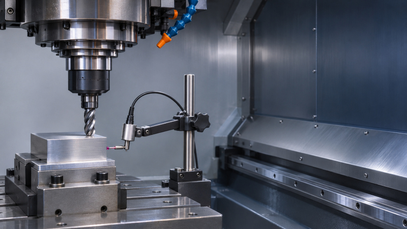
When a machined feature gradually moves out of tolerance during a long production run, the machine may be following its programmed path consistently while its structure changes temperature. Machine thermal stability affects accuracy because uneven heating and cooling alter the relative position and orientation of the tool and workpiece. A machine that is accurate when cold can therefore produce a different result after spindle warm-up, sustained cutting, or a change in room temperature.
The practical question is not whether a machine generates heat—all machines do—but whether the resulting displacement remains predictable and small enough for the tolerance, cycle time, and operating conditions. Evaluating that question requires measurements over time, not just a static positioning specification or a single inspection of a finished part.
From temperature change to dimensional error
Machine components expand or contract as their temperatures change. Uniform expansion is relatively straightforward to understand, but a machine tool rarely heats uniformly. A spindle may warm more quickly than its housing; one side of a column may receive sunlight while the other remains cool; a moving axis may heat a local section of its guideway. These temperature gradients can bend or tilt structural members as well as change their length.
The resulting error is the displacement between the cutting edge and the workpiece in the direction that matters to the feature being machined. Spindle growth along its axis may affect a pocket depth, while a small angular change in a column or spindle head can create a larger lateral error at a tool tip some distance away. The same temperature change can therefore have different consequences depending on machine geometry, tool projection, and the position of the axes.
Thermal drift can appear as a gradual change in diameter, depth, flatness, or location between successive parts. It can also affect the relationship between features produced at different times or machine positions. A stable offset may be corrected through a work or tool offset; a changing offset can make that correction obsolete before the next inspection.
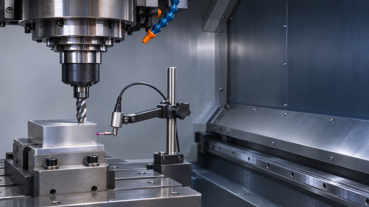
Heat sources that matter during machining
Spindle and drive systems
Spindle bearings, the motor, and associated components generate heat during rotation. The thermal response depends on speed, duration, load, lubrication, cooling, and the preceding operating state. A spindle run at a constant speed may approach a relatively steady condition, while a production cycle that repeatedly changes speed may never reach the same state as a simple warm-up routine.
Axis motors, ball screws, linear guides, and rotary drives also contribute. Repeated motion over one portion of an axis can produce a different temperature distribution from travel over the full stroke. On a multi-axis machine, heating around a rotary table or pivot can change the relationship between the programmed rotation center and the actual cutting position.
Cutting, coolant, and the surrounding environment
Cutting energy enters the chip, tool, workpiece, coolant, and machine in proportions that depend on the process. A thin or poorly supported workpiece may change shape as its temperature rises or as residual stresses are released. Coolant can remove heat, but its temperature, flow, and delivery pattern also influence the thermal condition of the tool, part, and nearby machine surfaces. A coolant system that cycles on and off may introduce a repeatable but significant temperature variation.
Room temperature is only part of the environmental picture. Air currents, doors, nearby equipment, direct sunlight, and temperature differences between the floor and upper machine structure can create gradients even when a central thermostat indicates a stable room. Foundation and enclosure temperatures may respond more slowly than the air, so a short ambient measurement does not necessarily describe the machine’s thermal history.
Separate thermal drift from other causes
A changing part dimension is evidence of a problem, not proof of a machine thermal error. Tool wear, tool seating, cutting-force deflection, fixture movement, workpiece heating, and inspection conditions can produce similar trends. Start by recording the dimension against time and cycle number, together with spindle speed, axis activity, coolant state, and any offset changes. Preserve the sequence of measurements: averaging the first and last parts together can hide a directional drift.
Then compare the observed pattern with the operating sequence. A change that follows spindle start-up and partially reverses after the spindle stops supports a thermal hypothesis. A dimension that changes mainly with tool life may point toward wear. An error that varies with cutting load may involve deflection. These are diagnostic clues rather than conclusive tests; more than one mechanism can act at the same time.
Where practical, measure machine displacement without cutting and compare it with results from a controlled cutting trial. A non-cutting test helps isolate the machine response, while the cutting trial includes the tool, workpiece, fixture, and coolant. Check the measuring system as well: gauges, artifacts, and parts can all change temperature. Letting a part cool before inspection may be appropriate, but it must be done consistently and recorded, particularly when comparing it with an in-process measurement.
Design a thermal test around the intended duty
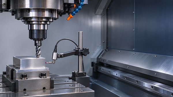
A useful evaluation begins with the feature and tolerance at risk. Identify which direction of relative tool-to-workpiece motion affects it, then choose a measurement arrangement sensitive to that direction. For a boring application, radial drift at the tool center may be more relevant than axial growth alone. For a depth-critical operation, axial movement and the timing of tool-length measurement deserve attention.
- Define the initial state. Record the machine’s preceding idle period, ambient conditions, coolant condition, and any warm-up or compensation already applied. “Cold” should describe an observable starting condition, not an assumption that every component has reached room temperature.
- Reproduce the operating sequence. Specify spindle speeds, axis motions, pauses, tool changes, coolant operation, and test duration. Include the production duty cycle where possible; an unloaded spindle test alone will not capture every cutting-related heat source.
- Measure displacement over time. Use suitable calibrated instrumentation and a stable reference arrangement. Record direction, sign convention, sampling interval, machine position, and relevant temperatures. Examine the transient response as well as the final reading.
- Repeat under defined conditions. Compare runs from similar starting states and, where relevant, after shutdown or a change in operating mode. Differences between runs help reveal whether a correction can be predicted reliably.
- Relate the result to the part. Determine how the measured motion transfers to the actual tool length, workpiece position, and feature direction. Verify the inference with a representative machining and inspection procedure when the decision is consequential.
A test that ends immediately after warm-up may miss drift during a long cycle, a shift in equilibrium after a speed change, or a reversal during a break. Conversely, a long test at one fixed condition should not be treated as evidence for every operating mode. The duration and sequence should cover the transitions that matter to the intended application.
Read thermal specifications in context
A reported displacement value is useful only with its test conditions. Ask whether it describes peak-to-peak variation, maximum deviation from the starting position, a final displacement, or a compensated residual. Confirm the measurement direction and location, spindle speed and loading, ambient conditions, test duration, and whether cooling and thermal compensation were active. Two values stated in the same units are not necessarily comparable.
ISO 230-3 addresses determination of thermal effects on machine tools and provides a framework for thermal testing. A reference to that standard does not by itself establish that a machine will hold a particular part tolerance. Review the actual test procedure and reported conditions, including any departures from the standard. Other applicable acceptance requirements should be agreed for the specific machine and application rather than inferred from a general standards claim.
Positioning accuracy and repeatability specifications also answer different questions. Repeatability describes the consistency of returning to a position under defined test conditions; accuracy concerns closeness to the intended position under those conditions. Neither value alone defines thermal performance over a production shift. Geometric errors, measurement uncertainty, cutting forces, and thermal drift may all consume part of the available tolerance. They should not simply be added or combined statistically without understanding their directions, dependencies, and measurement definitions.
Control the cause before relying on correction
Warm-up routines can reduce the difference between the initial and normal operating states, but their effectiveness depends on whether they resemble the relevant duty. Running the spindle without axis motion, coolant, or cutting may leave important components at a different temperature from their production state. A routine should be checked against the drift it is intended to control, especially after long idle periods or changes in shift pattern.
Temperature-controlled spindle cooling, managed coolant temperature, enclosure design, and control of local airflows can reduce the size or variability of thermal disturbances. These measures have different boundaries: cooling a spindle does not necessarily stabilize a column exposed to uneven ambient heating, and controlling room air does not eliminate heat generated inside the machine. Maintenance matters too; restricted cooling flow or a changed coolant condition can alter a previously established response.
Thermal compensation uses measured or modeled temperatures and operating conditions to adjust commanded positions or offsets. It can reduce predictable error, but sensors measure temperature at selected locations rather than deformation at every cutting point. A model established for one combination of speed, travel, and cooling may be less effective under another. Evaluate compensated and, where available, uncompensated behavior, and check how the system responds after interruptions or operating changes.
Frequent probing or offset updates can manage residual drift when the feature is accessible and the measurement method is reliable. They do not automatically correct changing tool wear, part deformation, or a biased probe. Set an update interval from observed drift and measurement uncertainty, and verify that the correction is applied to the appropriate axis and feature.
For acceptance, define an allowed thermal contribution to the error budget and test it under agreed starting conditions and production-relevant transitions. A machine whose drift is small but erratic may be harder to manage than one with a larger, repeatable displacement that a validated process can correct. The deciding evidence is the residual error at the workpiece, over the time and duty cycle in which the tolerance must actually be held.
Facing technical bottlenecks in manufacturing or looking for more efficient industrial solutions? Leave your details below and let the engineering experts at G-PME solve them for you.
We respect your privacy. Your information is strictly confidential.
Recommended News
 How to select manufacturing materials for high-temperature useMaterial selection for manufacturing guide: compare high-temperature materials by strength, creep, environment and fabrication to choose with confidence.
 What causes car electronics to drain the battery when parked?Car electronics can drain your battery while parked. Discover common causes, from hidden lights to faulty modules, and learn how to pinpoint the problem.
 How to compare machine tool prices across supplier quotesUnderstand machine tool market pricing and compare supplier quotes with confidence. Uncover hidden costs, assess performance, and negotiate better terms.
 How machine thermal stability affects machining accuracyMachine thermal stability directly affects machining accuracy. Discover how to measure thermal drift, evaluate test results, and maintain tighter tolerances.
 How to assess an industrial machining factory's inspection processAssess an industrial machining factory’s inspection process with practical checks for measurement methods, traceability, sampling, and quality records.
 Can AI CNC programming reduce setup time in European factories?Can AI CNC programming in Europe reduce setup time? Discover where it saves effort, what affects results and how to run a practical factory pilot.
 Which medical scrubs are most comfortable for long shifts?Find comfortable medical scrubs for long shifts. Compare fabrics, fit, breathability, and practical features to choose a set that moves with you all day.
 How to compare quotes from shipping agentsCompare shipping agents with confidence. Learn how to assess total costs, hidden fees, Incoterms, insurance, and cargo handling before you book.
 Can a manufacturing capability assessment identify capacity risks?A manufacturing capability assessment can uncover bottlenecks and capacity risks before they delay your project. Discover how to evaluate suppliers and protect delivery dates.
 How supplier sourcing solutions support incoming quality inspectionExplore supplier sourcing solutions quality assurance practices that strengthen incoming inspections, improve traceability, and reduce supply risks.
 How to verify FDA clearance when choosing an aesthetics device supplier in the USAChoosing an aesthetics devices supplier in USA? Learn how to verify FDA records, match device configurations, and compare costs with confidence.
 How technical specification support helps verify semiconductor compatibilityTechnical specification support for semiconductors helps verify compatibility, identify hidden risks, and guide confident component selection. Explore the key checks.
 How to assess shelf life when buying bath bombs wholesaleBuying bathbombswholesale? Learn how to assess shelf-life claims, packaging and remaining selling time to protect margins and make smarter purchasing decisions.
 How reshoring affects CNC industry investment in the USAExplore how reshoring shapes CNC industry investment in the USA, from machine purchases and automation to supply chain risks and smarter capital decisions.
 How to keep application engineering support documentation currentKeep application engineering support documentation current with practical guidance on ownership, change control, supplier updates, and reliable handovers.
 When is a scraper chip conveyor system suitable for CNC swarf?Is a scraper chip conveyor system right for your CNC swarf? Explore chip types, coolant filtration, capacity and wear to make a confident choice.
 How to size a CNC surface grinding machine for your workpiecesChoose the right surface cnc grinding machine with practical guidance on travel, clearance, load capacity and accuracy for your workpieces.
 How application engineering support improves product selectionApplication engineering support improves product selection by aligning specifications with real operating conditions. Discover how to compare options with confidence.
 What affects the price of an industrial air compressor?Understand what affects air compressors price, from capacity and controls to installation and energy costs. Compare quotes and choose the best-value system.
 How to check whether a bulletproof vest is NIJ certifiedLearn how to verify bulletproofvests on the official NIJ Compliant Products List, match labels and configurations, and avoid misleading certification claims.
 How to verify organic cotton baby clothes certificationShopping for organiccottonbabyclothes? Learn how to verify GOTS and OCS claims, check certificate details, and choose baby clothing with confidence.






Search News
Popular Tags