
Do Complex Electronic Components Need 5-Axis Machining?

Complex electronic components do not automatically need 5-axis machining. Housings with accessible pockets, straight connector bores, and flat mounting faces often remain economical on 3-axis equipment. Five-axis machining becomes valuable when angled features, restricted tool access, or relationships between several faces make repeated setups expensive or difficult to control. Simultaneous 5-axis cutting is justified by a narrower set of geometries that require the tool orientation to change during the cut.
How much does 5-axis machining cost compared with 3-axis machining? There is no reliable universal premium. A higher machine-hour rate can be offset by fewer fixtures, shorter tools, reduced handling, or less rework. Conversely, a straightforward enclosure gains little from additional axes if its features are already accessible in a simple setup. The useful comparison is total cost per accepted component, including programming, workholding, machining, inspection, and losses.
Separate electronic function from machining geometry
“Complex electronic component” describes several different manufacturing problems. A semiconductor package, printed circuit board, and machined shielding enclosure belong to different process categories. Axis selection matters primarily for the mechanical parts surrounding or supporting the electronics: connector bodies, instrument housings, cold plates, heat sinks, mounting frames, and similar hardware.
Even within those parts, functional complexity does not establish machining difficulty. An enclosure containing many circuit boards may have only rectangular pockets and perpendicular holes. A small connector housing with angled intersecting bores may demand more elaborate positioning despite having fewer features.
The useful starting point is a feature-access review. Identify the direction from which each surface, hole, and pocket must be machined, then establish which dimensions connect those features. Several accessible faces with loose relationships are a different problem from several faces whose bore positions must remain closely aligned to a common datum.
Three machining routes, with different reasons to use them
A 3-axis machine moves its cutting tool along three linear axes. Additional faces become accessible through refixturing or dedicated fixtures. An angled hole therefore does not automatically require a 5-axis machine; an angled fixture may provide a practical solution.
Indexed 5-axis machining, often called 3+2 machining, adds rotary positioning. The workpiece or tool is oriented and held at an angle while a conventional three-axis cut takes place. This suits many electronic housings with ports, mounting pads, and connector openings on several faces.
During simultaneous 5-axis machining, rotary and linear axes move together through the cutting path. This is useful when tool orientation must change continuously to follow a surface, avoid interference, or maintain access. A machine with five axes does not need to use simultaneous motion for every feature.
For a housing with features on its top and several sides, indexed machining deserves evaluation before simultaneous machining. The geometry may require several orientations without requiring any continuous rotary motion during cutting.

Where the extra axes earn their cost
Closely related features on different faces
Consider a connector body with a locating bore on one face and a mating interface on another. If their positional relationship is tight, separate setups require careful transfer of the datum reference. Chips beneath a locating surface, inconsistent seating, or fixture variation can consume part of the tolerance budget.
Machining both features in one clamping reduces those particular error sources. It does not guarantee accuracy: rotary-axis calibration, thermal stability, cutting forces, and measurement uncertainty remain relevant. The benefit is strongest when the avoided setup directly affects a required geometric relationship.
Deep features with obstructed access
A deep housing pocket may force a long tool to reach past a wall or fixture. Greater overhang reduces stiffness, increasing susceptibility to deflection and chatter. Tilting the component can open a shorter approach and allow a more rigid tool assembly.
This advantage requires a collision-free path for the complete tool assembly, including its holder and spindle envelope. Tilting does not solve every deep-pocket problem, and some internal corners or undercuts remain inaccessible. The actual tool-and-fixture arrangement must be evaluated before assigning a cost saving.
Surfaces that require changing orientation
Simultaneous machining becomes relevant for curved thermal interfaces, contoured internal surfaces, or other features where continuous tool orientation improves access. Merely having a curved surface is insufficient justification: many three-dimensional surfaces are machinable with a fixed tool axis. The deciding issue is whether that approach causes unacceptable reach, interference, surface quality, or machining time.
When 3-axis machining remains the better choice
A rectangular aluminum enclosure with an open internal pocket, a flat sealing land, and perpendicular mounting holes is a strong 3-axis candidate. If the opposite face requires only simple finishing, a second setup may still cost less than programming and proving the part on more expensive equipment.
Repeated production also changes the comparison. A dedicated fixture can make a previously awkward operation quick and repeatable. Multiple parts arranged in a fixture can spread handling time across a batch, while a rotary setup may restrict the number of components that fit within the available working envelope.
Dense heat-sink fins illustrate another limit. Their machining difficulty may arise from narrow slots, tool diameter, chip evacuation, and fragile walls. Extra axes do not remove those constraints. If the design allows it, an extruded blank or another near-net-shape process followed by selective machining may offer a stronger cost reduction than changing the machining center.
Thin enclosure walls present a similar distinction. Distortion can result from residual stress, clamping force, or an unbalanced material-removal sequence. A five-axis machine does not inherently correct these problems; stock condition, support, roughing strategy, and finishing sequence still control the result.
Compare total cost without inventing a price multiplier
A meaningful quotation comparison separates one-time preparation from recurring production costs. Programming, fixture design, initial setup, and first-article verification affect a prototype differently from a repeat batch. Machine time alone leaves too much of the route unexplained.
A useful comparison is:
Cost per accepted part = total batch cost ÷ number of parts accepted.
Total batch cost includes material, programming, fixtures, setup, machining, handling, finishing, inspection, and any actual scrap or rework. When evaluating a proposed route, use documented production experience for loss assumptions rather than assigning an unsupported rejection percentage.
The economic threshold follows from the same logic. Five-axis machining pays for itself when the value of eliminated setups, fixtures, cutting time, handling, and quality losses exceeds its additional programming, verification, and machine charges. Each term must relate to the same drawing revision, quantity, material condition, and acceptance requirements.
Some quotation details are especially revealing:
- What does the machine rate include? Labor, setup, overhead, and inspection may be bundled differently, making apparently similar hourly figures difficult to compare.
- A shorter cutting cycle does not establish a lower batch cost if programming and prove-out increase substantially.
- Fixture reuse matters. An established 3-axis fixture changes the economics of a repeat order; a new design requiring several custom fixtures creates a different comparison.
- Inspection effort follows the required evidence. Consolidating operations can simplify some measurements, but inaccessible features or complex datum relationships can still require a substantial inspection plan.
For a prototype, preparation effort can dominate. For recurring production, cycle time, fixture capacity, tool life, and repeatable acceptance carry more weight. The least expensive route can therefore change with quantity even when the part geometry stays unchanged.
Tolerances and materials can reverse the decision
A tight tolerance is not, by itself, a reason to specify five axes. A precision bore produced along a stable spindle direction may be well suited to a 3-axis process. Tight positional relationships between angled bores create a stronger argument for machining them within a common clamping.
Drawing requirements should distinguish feature size, location, orientation, and surface texture. A close bore diameter and a close relationship between two bores demand different process controls. Applying tight general tolerances to every surface can add finishing and inspection work without improving electrical assembly or thermal performance.
Material influences the value of improved access. Aluminum housings often allow productive cutting, but slender walls and long tools still limit stability. Copper thermal components introduce concerns around burr formation, tool adhesion, and surface finish. Harder or less machinable alloys increase the importance of tool loading and stiffness. None of these materials independently establishes a need for five axes.
Finishing also belongs in the dimensional plan. Anodizing, plating, and other specified treatments can affect fit, electrical contact areas, and sealing surfaces. Machining every feature in one setup does not eliminate the need to allocate tolerances across subsequent processing.
Make the process choice visible in the quotation
A useful comparison starts with the same solid model and controlled drawing, including material condition, critical datums, surface requirements, finishing, and order quantity. The proposed routes should explain their setup count and identify which relationships are maintained within one clamping. A quotation labeled simply “5-axis” reveals little about whether the proposed work uses indexing or simultaneous cutting.
For an angled connector housing, the comparison might be between separate angled fixtures on a 3-axis machine and indexed access on a 5-axis machine. For a contoured cooling component, the relevant comparison may involve fixed-axis tool reach versus continuous tool orientation. These are different engineering decisions and should have different cost explanations.
Where a feature drives a substantial premium, a small design change deserves attention: opening access to a pocket, changing a hole direction, or relaxing a nonfunctional relationship can alter the required process. The selected machining route should follow the component’s access and accuracy requirements, with its cost advantage demonstrated in the proposed operations.
Recommended News
 How to verify organic cotton baby clothes certificationShopping for organiccottonbabyclothes? Learn how to verify GOTS and OCS claims, check certificate details, and choose baby clothing with confidence.
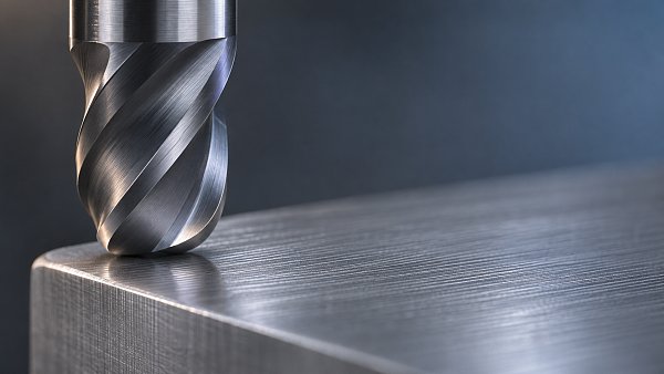
 How corner radius carbide end mills reduce edge chippingDiscover how corner radius carbide end mills reduce edge chipping, improve machining consistency, and support longer tool life with the right geometry and setup.
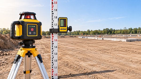
 How to choose a laser level for outdoor workCompare laserlevels for outdoor work by range, accuracy, durability, and receiver compatibility. Find the right tool for reliable results on site.
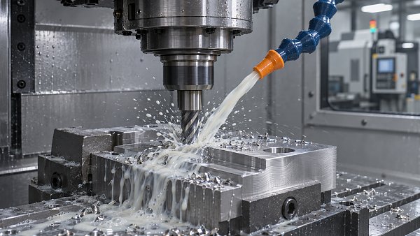
 Global Metal-Cutting Semi-Synthetic Coolant Market Forecast to Reach $1.73 Billion by 2030The semi-synthetic metal-cutting coolant market is forecast to reach $1.73 billion by 2030. Explore growth drivers and key considerations for buyers and suppliers.
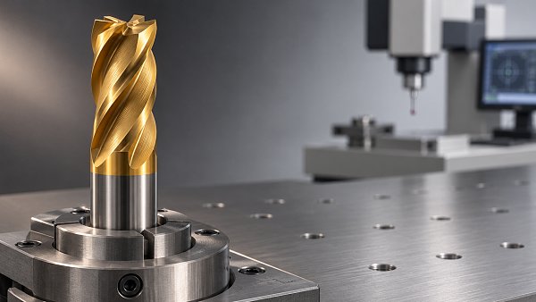
 How coating thickness affects carbide tool coating costsCarbide coating cost analysis: discover how thickness affects tool prices, wear and cost per part, and learn when a premium coating is worth the investment.
 What pressure stability data should a pump supplier provide?How do I shortlist the right high-pressure pumps supplier for stable pressure? Learn which test data to request and compare bids with confidence.
 How to evaluate an industrial supplier's delivery reliabilityStrengthen industrial procurement support and supplier evaluation with practical checks for delivery records, lead times, capacity, and recovery plans.
 Stonepeak Completes 65% Castrol Acquisition; Former Shell CEO to ChairStonepeak's 65% Castrol acquisition brings new leadership as former Shell CEO Ben van Beurden becomes chair. Explore potential implications for lubricant buyers and suppliers.
 How to inspect welded iron pipes for seam defectsInspect weldedironpipes for seam defects with a practical guide to visual checks, NDT methods, acceptance criteria, and safe repair decisions.
 How to assess electronics manufacturing solutions in North America for production capacityAssess electronics manufacturing solutions North America teams can rely on. Compare capacity, supply risks and quality controls to choose the right production partner.
 How to reduce thermal cracking in die casting mold insertsReduce thermal cracking in die casting mold inserts with practical tips on temperature control, cooling, steel selection and maintenance to extend tool life.
 Can portable telemedicine devices work with poor connectivity?Telemedicine hardware portable devices can support care with poor connectivity. Discover what works offline and how to evaluate reliable remote care workflows.
 How to choose rugs and carpets for high-traffic roomsDiscover how to choose rugs and carpets for high-traffic rooms. Compare materials, construction, cleaning needs, and fit to find a practical, lasting option.
 What affects the wholesale price of EPS sandwich panels?Compare EPS sandwich panels wholesale prices and discover how core density, steel facings, order size, and delivery costs affect your project budget.
 Japan's Machine Tool Export Controls Accelerate China's Five-Axis SubstitutionJapan's machine tool export controls are accelerating China's five-axis CNC substitution. Explore the implications for buyers and supply chains.
 Why do automatic mechanical watches stop when not worn?Why do automaticmechanicalwatches stop when unworn? Discover how power reserve works, how to restart your watch, and when to seek professional help.
 Choosing high-tensile bolts for industrial fastening in EuropeIndustrial fastening Europe: Learn how to select high-tensile bolts, coatings and standards for reliable joints, accurate preload and safer assembly.
 How does excess inventory affect fashion retail profitability?Discover how excess inventory erodes fashion retail profits through markdowns and holding costs, and learn practical ways to protect margins and free up cash.
 US Adds 50% Section 338 Tariff on Canadian Seals and Other ProductsUS Section 338 tariffs add 50% to covered Canadian seals, lubricants and other goods. Explore the potential impact on sourcing and supply chain costs.
 Can lean manufacturing reduce changeover time in injection molding?Discover how lean manufacturing can reduce injection molding changeover time with SMED, better preparation, standardized processes, and quality controls.
 How to estimate the payback period for a CNC machining centerEstimate your CNC machining center investment payback with a practical formula, installed cost checklist, cash-flow examples, and risk analysis.






Search News
Popular Tags