
What causes mechanical seal failure in desalination plants?
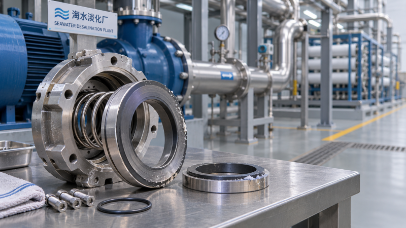
Mechanical seal failure can disrupt desalination operations, increase maintenance costs, and put pumps at risk. Identifying the cause is essential to preventing repeat failures.
In desalination plants, seals face abrasive particles, inadequate lubrication, corrosion, and pressure fluctuations. The most useful diagnosis connects the damaged seal to operating conditions before the failure.
For maintenance teams, the immediate priority is to determine whether leakage is caused by the seal itself, its support system, the pump, or the process.
Replacing a seal without checking these conditions may restore operation temporarily, but the same failure can return. Use the checks below to identify the mechanism and prevent recurrence.
What usually causes mechanical seal failure in desalination plants?
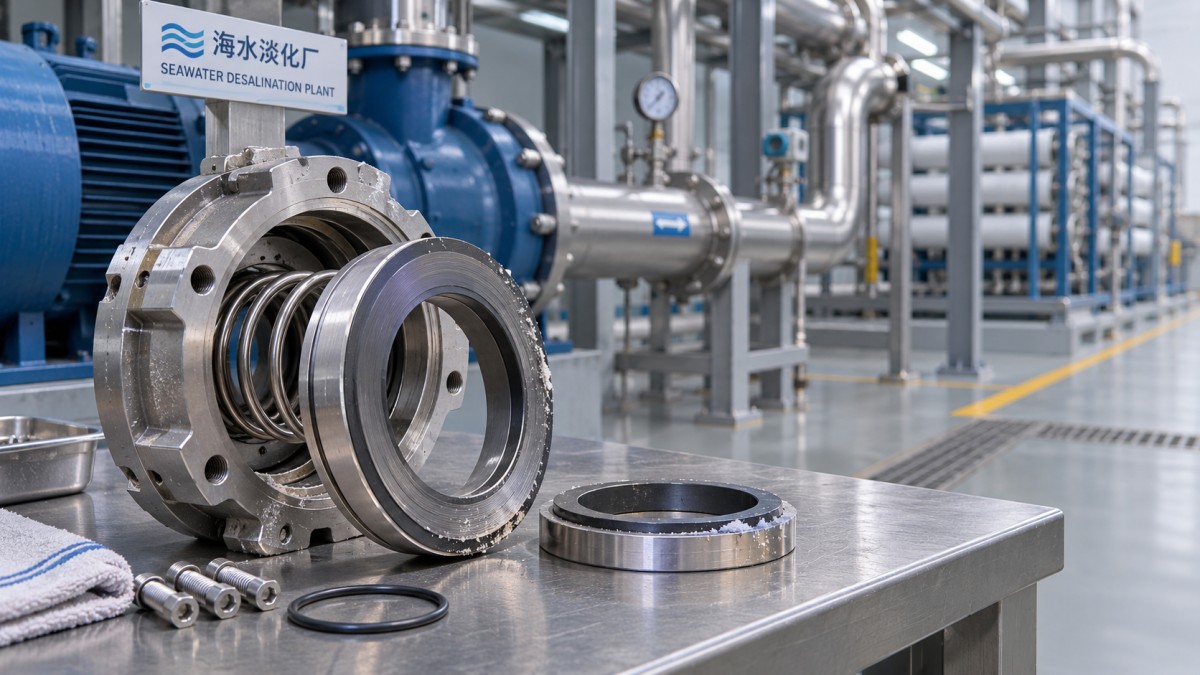
Most failures begin when the seal faces lose their lubricating liquid film, become contaminated, or move outside their intended operating conditions. Several causes often occur together.
For example, blocked flush piping can increase face temperature, while abrasive particles accelerate wear. A pump restart after low suction flow may then produce a visible leak.
The main causes maintenance teams should investigate are dry running, solids contamination, corrosion, unsuitable materials, pressure disturbances, shaft movement, and installation errors. Start with the evidence.
Record when leakage began, whether it appeared suddenly or gradually, and what changed beforehand. Startup events, cleaning cycles, process upsets, and recent repairs are particularly valuable clues.
Do not assume that the visibly damaged component caused the failure. A cracked face may be the final result of overheating, vibration, or incorrect assembly.
Which symptoms point to the likely failure mechanism?
Leakage rate, seal temperature, vibration, and the timing of the leak provide a useful first screen. Compare readings with the pump’s normal baseline and manufacturer limits.
- Sudden leakage after startup: Check for dry running, inadequate venting, incorrect rotation, pressure shock, or installation damage.
- Leakage that increases gradually: Investigate abrasive wear, corrosion, deposits, shaft movement, and deterioration of secondary seals.
- High seal-area temperature: Check liquid supply, cooling, flush flow, operating pressure, and whether the liquid may be vaporizing.
- Leakage accompanied by vibration: Investigate bearings, alignment, cavitation, pipe strain, and operation outside the pump’s recommended range.
- Leaks after cleaning: Review chemical concentration, temperature, exposure time, and compatibility of all wetted seal materials.
These patterns are starting points, not definitive diagnoses. Confirm the suspected cause by inspecting the removed components and reviewing actual process and maintenance records.
If leakage creates an immediate hazard, follow the site’s shutdown and isolation procedures. Collect operating evidence only when it is safe to do so.
How does dry running damage a mechanical seal?
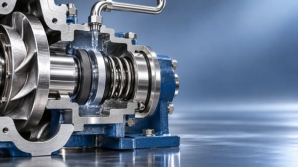
Seal faces normally rely on a thin liquid film for lubrication and heat removal. When that film disappears, friction can quickly raise face temperatures.
Common triggers include starting an unvented pump, low suction levels, air ingress, an interrupted flush supply, or operating before the seal chamber fills with liquid.
Overheating may also occur when liquid at the seal faces vaporizes because local pressure falls or temperature rises. The chamber can contain liquid while lubrication remains inadequate.
Look for heat discoloration, cracked or blistered face surfaces, heat-damaged elastomers, and leakage appearing shortly after startup. The exact appearance depends on the face materials.
Check suction pressure, tank level, venting arrangements, and the startup sequence. Review trends around the event rather than relying only on readings taken after shutdown.
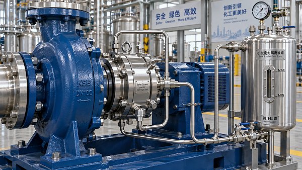
Where fitted, verify flush or barrier-fluid flow, pressure, and temperature against the seal supplier’s requirements. A pressure gauge alone does not prove adequate flow.
Before restarting, correct the supply problem and confirm the chamber is filled and vented according to the equipment instructions. Check interlocks and operator procedures for repeat events.
How do sand, scale, and corrosion products cause seal leakage?
Seawater intake particles, filter carryover, scale fragments, and corrosion products can enter the seal environment. Even small particles may damage faces or restrict seal movement.
Hard particles trapped between faces can score their surfaces and interrupt the liquid film. Deposits around springs or sliding components can prevent the seal from following shaft movement.
Inspect for circumferential scoring, embedded debris, chipped faces, clogged flush passages, and deposits on moving parts. Preserve samples before cleaning if their source is uncertain.
Compare the debris with intake sediment, cartridge filter deposits, pipe scale, and corrosion products. A laboratory analysis may be worthwhile when failures recur or deposits are difficult to identify.
Then trace the contamination upstream. Check intake screening, filtration condition, recent piping work, flushing practices, and any process change that could have released accumulated scale.
Clean and inspect the seal support piping, including strainers and flow restrictions where installed. Confirm that any filtration arrangement is suitable for the fluid and seal design.
A finer filter is not automatically the right fix: excessive restriction can reduce the flow needed to protect the seal. Consult the equipment supplier before changing the arrangement.
Can seawater chemistry or cleaning chemicals attack seal materials?
Chloride-rich seawater can challenge metallic components, especially where oxygen levels, temperature, crevices, or deposits promote localized corrosion. Conditions vary significantly between services.
Check springs, sleeves, retainers, and other wetted metal parts for pitting, crevice attack, cracking, or loss of section. Identify the affected component and its specified alloy.
Elastomers and seal faces also need compatibility checks. Swelling, hardening, cracking, extrusion, or loss of elasticity may indicate chemical exposure, temperature damage, pressure effects, or aging.
Review the full operating envelope, including seawater, concentrated brine, cleaning solutions, disinfectants, and preservation chemicals. Cleaning-in-place conditions may be more severe than normal production.
Record actual chemical concentration, exposure time, temperature, and cleaning sequence. Compare them with material compatibility data and the seal manufacturer’s recommendations for the complete seal assembly.
Do not select a replacement solely because one material resists seawater. Confirm compatibility of every wetted component with all credible operating, cleaning, and shutdown conditions.
Why do pressure fluctuations and vaporization matter?
High-pressure reverse osmosis service can expose seals to substantial differential pressure, while starts, stops, valve movements, and process disturbances can introduce rapid changes.
Depending on seal design, pressure outside the specified range can overload faces, deform components, damage secondary seals, or disrupt the conditions needed for stable lubrication.
Low pressure can be just as significant if it allows liquid at the faces to vaporize. Check pressure and temperature together against the fluid’s operating conditions.
Review trends at startup, shutdown, and transitions between operating modes. Short pressure spikes may be missed by routine manual readings or slow recording intervals.
Inspect control valves, minimum-flow arrangements, suction conditions, and pressure protection devices. Confirm the seal’s pressure rating and allowable operating envelope with its manufacturer.
For dual seals, check the specified pressure relationship between the process and buffer or barrier system. The correct relationship depends on the seal configuration and support plan.
When is the pump or installation responsible?
A seal may fail because the pump cannot keep its rotating and stationary components correctly positioned. Excessive vibration, shaft deflection, or bearing wear can disturb face contact.
Check shaft runout and axial movement using the pump and seal manufacturers’ measurement methods and limits. Inspect bearings, coupling condition, alignment, and the shaft sleeve.
Investigate pipe strain and foundation condition when alignment changes after piping is connected. Also review whether the pump operates near its intended flow range.
Cavitation or unstable suction can produce vibration and pressure fluctuations that affect seal reliability. Confirm the cause through suction measurements and pump inspection before changing the seal.
Installation errors can produce immediate leakage or shorten service life. Common examples include damaged elastomers, contaminated faces, incorrect setting dimensions, and uneven gland tightening.
For cartridge seals, follow the supplier’s sequence for setting, tightening, removing setting clips, and checking rotation. Procedures differ, so use the instructions for the installed model.
During assembly, keep faces clean and protect elastomers from sharp edges. Use only assembly lubricants approved for the seal materials and the fluid service.
What should maintenance teams check before replacing a failed seal?
A repeatable inspection process helps distinguish a defective seal from a system problem. Capture evidence before cleaning or discarding parts, and document each finding.
- Make the equipment safe. Isolate, depressurize, drain, and verify the equipment according to site procedures before opening the pump or support system.
- Record the failure history. Note installation date, operating hours, leak onset, process conditions, previous repairs, and recent changes to operation or cleaning.
- Inspect the support system. Check available flow, pressure, temperature, blockages, leaks, and instrument condition against the applicable seal plan and supplier requirements.
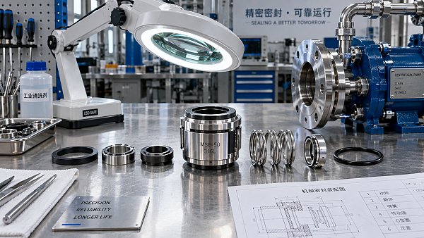
- Examine the removed seal. Photograph both faces and secondary seals; record scoring, cracking, deposits, corrosion, and the location of damage.
- Measure pump condition. Check shaft and sleeve surfaces, runout, axial movement, bearings, alignment, and vibration where practical and specified.
- Verify the replacement. Confirm dimensions, pressure and temperature limits, materials, rotation requirements, and compatibility with normal and cleaning fluids.
- Correct the underlying issue. Repair the identified support-system, process, pump, or installation problem before returning the equipment to service.
- Monitor the restart. Vent and start according to approved procedures, then trend leakage, temperature, pressure, flow, and vibration against the established baseline.
Keep the removed parts until the investigation is complete. When the cause remains unclear, share photographs, operating data, and component history with the seal supplier.
How can after-sales teams prevent repeat failures?
Prioritize the failure modes supported by evidence. A recurring flush blockage calls for a different corrective action from repeated damage caused by shaft movement or chemical exposure.
Set inspection intervals around actual risk and failure history. Track seal life, leakage trends, support-system performance, and the operating events associated with each replacement.
Maintain accurate records of seal configuration, material grades, support plans, and approved spare parts. Similar-looking seals may have different pressure limits or chemical compatibility.
Coordinate with operators when failures occur during startup, shutdown, or cleaning. A revised venting sequence, verified interlock, or controlled cleaning procedure may prevent another event.
Mechanical seal reliability in desalination plants depends on the entire pump and process system. Use the damage pattern, operating history, and measured conditions together before selecting a remedy.
Facing technical bottlenecks in manufacturing or looking for more efficient industrial solutions? Leave your details below and let the engineering experts at G-PME solve them for you.
We respect your privacy. Your information is strictly confidential.
Recommended News
 What causes mechanical seal failure in desalination plants?Desalinationplants: discover why mechanical seals fail, how to diagnose leaks, and what maintenance teams can do to prevent repeat failures and protect pumps.
 PBI Seals Outlook to 2035: Aerospace and Fuel Cell Demand Drives GrowthPBI seals market outlook to 2035: Explore projected 5.8% annual growth, aerospace and fuel cell demand, and key insights for buyers and suppliers.
 How advanced materials improve wear resistance in mechanical sealsDiscover how advanced materials improve mechanical seal wear resistance, and learn to select the right face pair for abrasive, corrosive and demanding operating conditions.
 How to verify quality standards when selecting mechanical sealsProduct selection guidance for mechanical seals: verify quality standards, material traceability, certifications, and test evidence before you buy.
 What should mechanical seal technical specification documents include?Explore technical specification support documentation for mechanical seals, covering materials, drawings, standards, and testing to reduce risks and make confident supplier approval decisions.
 John Crane Signs Three-Year Agreement to Improve Phosphate Mine Seal ReliabilityJohn Crane's three-year agreement targets phosphate mine seal reliability with on-site expertise and mechanical seal solutions. Explore its potential to reduce downtime.
 How to select low-friction industrial seals for centrifugal pumpsChoose industrial seals for low friction in centrifugal pumps. Compare face materials, lubrication and support systems to reduce wear and operating losses. Find the right fit.
 John Crane to Showcase Emissions and Downtime Reduction Technologies at ADIPEC 2026John Crane at ADIPEC 2026: Explore technologies targeting lower emissions and compressor downtime, and discover what reported savings could mean for your operations.
 How Do You Select a Mechanical Seal for Chemical Service?How do I select a mechanical seal for chemical service? Explore material compatibility, single vs. dual seals, and support systems to reduce leakage risks and choose with confidence.
 Why Do Mechanical Seals Fail Prematurely?Why do mechanical seals fail prematurely? Discover how dry running, poor flushing, and misalignment cause leaks—and learn practical checks to prevent repeat failures and reduce downtime.
 When aerospace metal traceability certification is required for sealsAerospace metal traceability certification for seals: learn when it is required, which records matter, and how to protect compliance, quality, and release decisions.
 How to select mechanical seals for mixers handling abrasive slurriesMechanical seals for mixers: learn how to select durable seal arrangements, face materials, and support systems for abrasive slurry service.
 EU Adopts EN 1514-2:2026 for Mechanical Seals, Mandatory From September 2026EU Adopts EN 1514-2:2026 for Mechanical Seals: learn the key compliance changes, CE marking risks, and exporter actions required before the September 2026 deadline.
 How to Evaluate an Aerospace Seals Supplier for Material Traceability and Compliance RequirementsAerospace seals supplier selection starts with traceability and compliance. Learn how to assess records, cert control, and audit readiness before costly sourcing mistakes.
 China-Uzbekistan AEO Deal Speeds Precision ExportsChina-Uzbekistan AEO Deal speeds precision exports by cutting clearance time and compliance costs, helping exporters boost delivery reliability in Uzbekistan’s growing industrial market.
 Advanced CNC Machining Stainless Steel: How Tolerances Affect Seal PerformanceAdvanced CNC machining stainless steel directly impacts seal reliability. Learn how tolerances, surface finish, and inspection control leakage, wear, and performance.
 REACH Rule Takes Effect for PFAS in Mechanical SealsREACH Rule Takes Effect for PFAS in Mechanical Seals: learn how SVHC notification, SDS compliance, and EU export readiness may affect customs, delivery, and market access.
 What to Review Before Choosing an Aerospace Seals Manufacturer for AS9100 ProjectsAerospace seals manufacturer selection for AS9100 projects starts with risk, traceability, material control, and change management. Review key factors before approving a supplier.
 Industrial Sealing Systems in Europe: What to Check Before Supplier ApprovalIndustrial sealing systems Europe buyers can use this practical guide to verify compliance, traceability, technical fit, and supplier reliability before approval.
 How PTFE Industrial Sealing Systems Reduce Chemical Leaks in High-Pressure LinesPTFE industrial sealing systems help reduce chemical leaks in high-pressure lines by matching seal design, hardware condition, and installation control for safer, longer-lasting performance.
 EU REACH Adds PFHxA, PFHxS to SVHC ListEU REACH adds PFHxA and PFHxS to the SVHC list, raising SCIP and supply chain compliance risks for EU exporters. Learn what it means for seals, gaskets and casting processes.



Search News
Popular Tags