Mechanical Seal Documentation: A Practical Guide for Technical Evaluators
A mechanical seal specification is only as useful as its supporting evidence. Technical evaluators need documents that establish compatibility, define acceptance criteria, and support consistent supplier comparisons.
A complete package should identify operating conditions, seal configuration, materials, dimensional interfaces, applicable standards, auxiliary systems, and verified performance requirements for the proposed equipment and service.
Incomplete technical specification support documentation can conceal compatibility risks, particularly when suppliers present generic product ratings without identifying the conditions under which those ratings apply.
The essential review question is straightforward: can every critical requirement be traced to a proposed design, supporting evidence, and an agreed method of acceptance before release?
This guide explains what to request, where technical submissions commonly fall short, and how to distinguish an acceptable proposal from one requiring further engineering clarification.
What Documents Should You Require Before Approving a Seal?
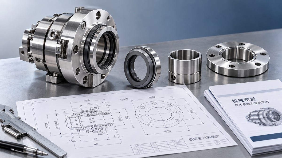
Start with an application-specific document register. A product brochure can establish general capability, but it cannot demonstrate suitability for a particular pump, fluid, or operating cycle.
Separate documents required for technical selection from records generated during manufacturing. Otherwise, evaluators may mistakenly demand final inspection evidence before the supplier has manufactured the equipment.
The following register provides a practical baseline. Adjust its scope according to service severity, contractual requirements, equipment criticality, and the consequences of leakage or failure.
Does the Datasheet Describe the Actual Operating Envelope?
Begin with the application rather than the catalog rating. Record the equipment tag, pump model, shaft speed, rotation direction, installation orientation, and intended duty cycle.
Define minimum, normal, and maximum seal-chamber pressures and temperatures. Distinguish these conditions from pump discharge pressure, which may differ materially from pressure at the seal.
Include startup, shutdown, standby, cleaning, and credible upset conditions. Specify whether reverse pressure, vacuum, pressure cycling, or loss of cooling can occur during these states.
Describe the fluid composition, concentration, viscosity, density, vapor pressure, and solids content at relevant conditions. Identify toxicity, flammability, crystallization, polymerization, and any tendency to form deposits.
State whether dry running, gas entrainment, flashing, or intermittent operation is expected. These conditions can change the required seal arrangement, face materials, and support-system design.
For variable-speed equipment, document the complete speed range and operating transitions. Request supplier confirmation of suitability across that envelope, including any restrictions on minimum speed.
Where inputs remain uncertain, record assumptions and the party responsible for confirming them. Unresolved fluid properties should remain visible technical issues until their consequences are assessed.
Is the Proposed Configuration Suitable for the Service?
The specification should identify the seal arrangement, cartridge or component construction, balanced or unbalanced design, and whether the design uses a rotating or stationary flexible element.
For dual seals, identify the function and pressure relationship of the intermediate fluid. Use buffer and barrier terminology consistently with the selected arrangement and governing standard.
Require the supplier to explain how the arrangement addresses leakage consequences, process conditions, and reliability needs. Configuration selection should follow an engineering basis documented for the application.
Ask for explicit operating limits covering pressure, temperature, speed, and relevant combinations. Separate maximum ratings do not establish that every maximum can occur simultaneously in service.
Where calculations support selection, request their inputs, assumptions, methods, and conclusions. Relevant assessments may include face loading, heat generation, pressure margin, and available heat removal.
Record restrictions such as required liquid lubrication, minimum circulation, or prohibited operating states. These restrictions must also appear in commissioning instructions and operating procedures where applicable.
Are Materials Identified Precisely Enough to Verify Compatibility?
A materials schedule should identify seal faces, secondary seals, springs, sleeves, glands, and other relevant components. Descriptions such as stainless steel or carbon are insufficient.
Specify alloy designations, elastomer compounds, face-material grades, and applicable material standards. Where performance depends on a proprietary grade, require its identification and relevant technical properties.
Evaluate compatibility against actual exposure conditions, including concentration, temperature, cleaning agents, and intermediate fluids. A generic chemical compatibility chart may provide screening evidence but needs application-specific interpretation.
For example, a material suitable for the process fluid may be unsuitable for cleaning chemicals. The review must cover both exposures and their respective temperatures.
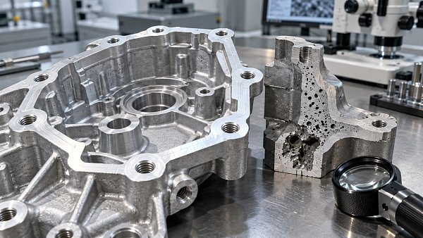
Request material certificates and traceability at the level required by the contract. Define which components require certificates, the certificate type, and acceptable links to supplied parts.
Where coatings, hardfacing, or special treatments are proposed, document the substrate, treatment specification, inspection requirements, and repair limitations. Review corrosion and wear resistance as separate considerations.
Will the Seal Fit the Equipment and Its Support System?
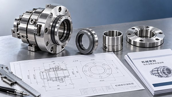
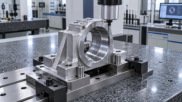
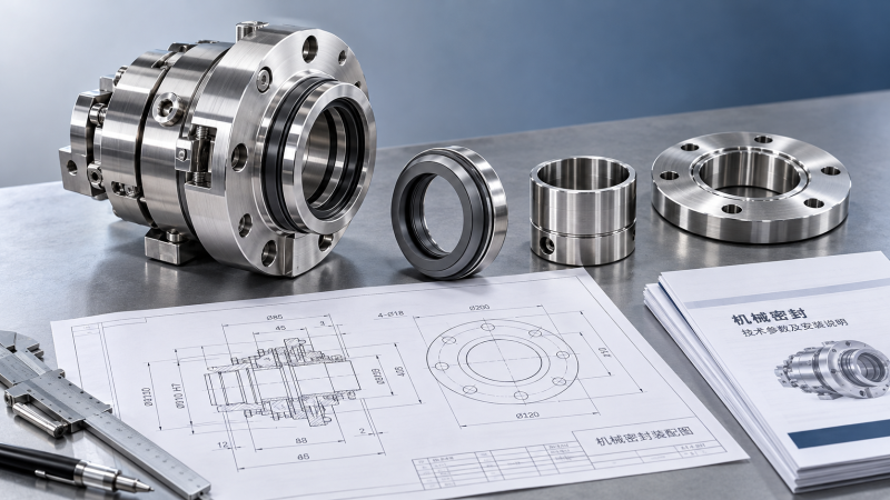
Approved interface drawings should show shaft or sleeve diameter, seal-chamber bore and depth, gland mounting details, axial setting, connection locations, and the required installation envelope.
Include dimensional tolerances, shaft runout limits, endplay limits, and relevant surface-finish requirements. Identify which requirements apply to the seal assembly and which apply to equipment interfaces.
For replacement seals, compare supplier drawings against verified equipment dimensions. An existing part number alone may not capture previous modifications or differences between nominally identical pumps.
Support-system documentation should identify the selected piping plan, connection sizes, flow direction, instruments, utilities, and operating requirements. State the applicable plan designation and its reference standard.
Depending on the arrangement, request fluid specifications, pressure settings, circulation requirements, reservoir details, cooler duty, and utility conditions. Explain how required conditions will be maintained.
Define alarms, trips, permissives, and operator responses where required by the system design. Provide setpoint rationale and identify responsibility for integration with plant control systems.
A seal requiring continuous cooling remains an incomplete selection until available cooling conditions are confirmed. Utility availability is therefore part of technical acceptance for that installation.
Which Standards Apply, and What Does Compliance Mean?
List each applicable standard by designation and edition, together with purchaser specifications and regulatory requirements. Avoid broad claims such as compliant with all international standards.
API 682 and ISO 21049 are relevant references for pump shaft sealing systems within their scope. Their applicability should follow the equipment, service, and contract.
Do not assume that citing either reference makes every clause applicable to every seal. Define the required classifications, arrangements, options, and supplemental purchaser requirements explicitly.
Where different standards or specifications overlap, establish an order of precedence. This helps resolve conflicts involving materials, testing, documentation, or auxiliary equipment before fabrication begins.
Require a clause-based compliance statement for significant requirements, supported by document references. Suppliers should identify deviations and exclusions clearly, including their technical consequences and proposed alternatives.
Qualification evidence also needs context: identify the tested design, materials, operating conditions, and configuration. Explain its relevance when the proposed seal differs from the tested assembly.
What Testing and Acceptance Evidence Is Actually Needed?
Agree on the inspection and test plan before relevant manufacturing activities begin. It should identify inspections, test procedures, acceptance limits, records, and purchaser involvement requirements.
Distinguish design qualification from production acceptance. Qualification supports a design’s demonstrated capability under defined conditions; production testing verifies specified attributes of the particular assembly being supplied.
Depending on scope, verification may include dimensional inspection, material identification, pressure testing, and leakage testing. Specify which components or assemblies each procedure covers and why.
Leakage requirements should identify the medium, pressure, temperature, speed where relevant, duration, measurement method, and acceptance limit. State whether acceptance concerns visible leakage or measured flow.
A static pressure test does not demonstrate dynamic sealing performance. Similarly, a test using one fluid cannot establish identical leakage behavior with every process fluid.
Completed reports should identify the seal or assembly, procedure revision, actual test conditions, results, instrument references, and disposition. Record deviations from the approved procedure explicitly.
For critical service, define witness or hold points according to project needs. Specify notification periods and release responsibilities so inspection arrangements support the manufacturing schedule.
How Should Evaluators Compare Suppliers and Close Documentation Gaps?
Use a compliance matrix that links each requirement to the supplier’s response, supporting document, revision, and review status. Keep commercial preferences separate from mandatory technical requirements.
Classify issues by their effect on selection and release. Missing operating-limit confirmation may prevent technical approval, while a minor drawing correction may permit conditional progress.
For example, two bids may offer the same nominal pressure rating. If only one confirms operation at the specified temperature, their documented suitability is different.
Request clarification against a specific requirement instead of asking for more information generally. Each clarification should identify the missing evidence and the decision it affects.
Maintain revision control across datasheets, drawings, calculations, and purchase requirements. When conditions change, assess which approvals and supporting documents must be updated before manufacture continues.
The final dossier should connect equipment tags, serial numbers, certificates, drawings, test records, and maintenance instructions. Include spare-part identification and any special installation or storage requirements.
Approve When the Evidence Supports the Application
Complete technical specification support documentation connects service conditions to design choices, then connects those choices to verification and acceptance. Document volume alone does not establish completeness.
Before approval, confirm that operating assumptions are resolved, interfaces are verified, materials are justified, support utilities are available, and testing has clear acceptance criteria and responsibilities.
Where critical evidence remains missing, define the gap and its release consequence explicitly. A defensible procurement decision rests on traceable engineering evidence for the actual application.