
How to set relubrication intervals for industrial maintenance
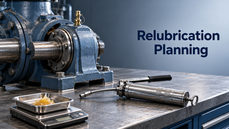
A bearing runs hot after a routine service visit. Was the grease added too late, or was too much added at once? Both mistakes are common in industrial maintenance, and either can turn a simple lubrication task into an unplanned shutdown.
The right relubrication interval starts with equipment manufacturer guidance—not a fixed calendar rule. Bearing design, operating speed, load, temperature, contamination, and grease delivery all influence how long a lubricant remains effective. For service technicians, the practical challenge is turning those variables into a schedule that can be followed, checked, and improved.
This guide focuses on grease-relubricated rolling bearings in motors, pumps, fans, conveyors, and similar rotating equipment. Oil-lubricated systems require separate decisions about oil condition, replenishment, filtration, and change intervals. Sealed-for-life bearings should not be added to a greasing route unless the manufacturer explicitly permits relubrication.
Start with the machine, not the grease gun
Before calculating an interval, confirm that the lubrication point is correctly identified. A fitting on a housing may feed a bearing directly, supply a housing cavity, or connect to a distribution system. Those arrangements do not necessarily require the same quantity or frequency.
Collect the following information from the equipment manual, bearing records, nameplates, and operating history:
- Bearing identification: designation, type, dimensions, and lubrication arrangement.
- Operating conditions: actual shaft speed, duty cycle, load, orientation, and measured temperature.
- Lubricant specification: approved grease, base-oil viscosity, thickener system, consistency grade, and compatibility restrictions.
- Environmental exposure: dust, water, washdown chemicals, process debris, and outdoor weather.
- Delivery details: manual or automatic application, line length, grease outlet arrangement, and prescribed replenishment quantity.
If the equipment manufacturer and bearing supplier give different recommendations, resolve the difference before changing the route. The equipment manufacturer may account for housing geometry, seals, cooling, and application conditions that a general bearing chart does not cover.
Build a defensible baseline interval
Use the manufacturer’s specified interval where available, checking the assumptions behind it. A recommendation based on moderate temperature and clean continuous operation may not suit a washdown conveyor or a heavily loaded fan near a furnace.
When equipment-specific guidance is missing, use the bearing manufacturer’s current lubrication tables or calculation tools. These commonly consider bearing type, dimensions, speed, load, and operating temperature. Enter actual service conditions rather than relying only on the machine’s rated capacity.
Read speed and bearing size together
Rotational speed alone is not enough. A large bearing at a given rpm has a different lubrication demand from a smaller bearing at the same rpm. Supplier methods may use a speed factor such as n × dm, where n is rotational speed in rpm and dm is mean bearing diameter in millimeters:
dm = (d + D) / 2
Here, d is bearing bore diameter and D is outside diameter. This factor helps identify the relevant operating range; it does not independently establish a relubrication interval. Bearing design, grease suitability, and the supplier’s calculation method still matter.
Separate running hours from calendar time
For equipment with variable utilization, operating hours usually provide a more useful starting point than a monthly schedule. However, idle equipment can still experience moisture ingress, corrosion, and lubricant deterioration. Follow any calendar limit specified by the manufacturer alongside the running-hour limit.
Consider an illustrative machine with an approved baseline of 2,000 operating hours. At 16 running hours per day, that is approximately 125 operating days. It is not automatically a four-month interval: shutdowns, weekend operation, and environmental limits affect the actual due date.
Adjust for what the bearing actually experiences
A baseline becomes useful only after it is checked against site conditions. Avoid applying arbitrary reductions for every unfavorable observation. Some supplier methods already incorporate temperature, load, or contamination corrections; applying them again can produce excessive lubrication.
Temperature deserves particular care. Grease life generally falls as operating temperature rises, but there is no universal correction valid for every formulation and bearing arrangement. A sudden temperature increase may indicate overgreasing, misalignment, excessive load, or damage—not simply a need for more lubricant.
Contamination also demands more than a shorter interval. If water repeatedly enters through a damaged seal, frequent greasing may temporarily reduce symptoms while leaving the failure mechanism untouched. Repair the ingress path and reassess the schedule afterward.
Set grease quantity alongside frequency
An interval without a replenishment quantity is an incomplete maintenance instruction. “Grease every month” leaves each technician to decide what enough looks like. The result can vary significantly between shifts and service visits.
Use the equipment manufacturer’s quantity whenever it is available. For some rolling-bearing applications, a commonly used estimate for replenishment quantity is:
G = 0.005 × D × B
In this expression, G is grease mass in grams, D is bearing outside diameter in millimeters, and B is bearing width in millimeters. This is an estimating method, not a universal instruction. It does not define the initial housing fill, and it may not suit every bearing arrangement or grease supply path.
For illustration, a bearing with a 100 mm outside diameter and a 20 mm width gives an estimated replenishment quantity of 10 g. Whether that quantity is appropriate must still be checked against the machine instructions, housing design, and grease delivery method.
Calibrate manual grease guns by weighing the discharge from several full strokes and calculating the average output. Record grams per stroke for each gun. “Five pumps” means little when guns deliver different quantities or a cartridge contains trapped air.
More frequent, smaller doses can be appropriate in some applications, particularly with automatic lubrication. However, dividing a manual dose into smaller portions does not automatically validate an automatic system. Delivery pressure, line resistance, grease pumpability, and distribution must also be verified.
Make the first service cycles a controlled trial
When introducing a new interval, treat it as a documented starting point rather than a permanent answer. Critical equipment should have an approved monitoring plan, clear escalation criteria, and appropriate engineering oversight.
Record a baseline under representative operating conditions. Useful measurements include bearing housing temperature, vibration trends, ultrasonic readings where applicable, and observations of seals or grease discharge. Note speed, load, and ambient conditions so later comparisons are meaningful.
During lubrication
Clean the fitting and grease-gun connection before connecting. Verify the lubricant identity, prescribed quantity, and correct lubrication point. Follow the equipment procedure for any grease outlet or relief arrangement; do not remove plugs indiscriminately.
Some approved procedures require lubrication while equipment is operating to distribute grease. Only perform this where the machine design, guarding, site rules, and task risk assessment permit safe access. Otherwise, isolate the equipment using the required lockout/tagout procedure. Never reach through guards or approach exposed rotating components to complete a lubrication task.
Stop and investigate unexpected resistance. A blocked fitting, hardened grease, restricted line, or closed outlet should not be overcome by forcing more pressure into the housing.
After lubrication
Check the response over a suitable observation period. Persistent heating, leakage, or increased vibration needs investigation. Ultrasonic monitoring can help identify changes in friction during greasing, but readings depend on instrument setup, access point, operating conditions, and technician technique. Use it alongside other evidence—not as a universal instruction to keep adding grease until a reading falls.
Refine the interval from evidence, not habit
Adjust one variable at a time where practical. If both quantity and interval change together, it becomes harder to identify which change improved or worsened the result.
- Consider a shorter interval when repeated observations show lubricant starvation before the scheduled service, after confirming correct delivery and lubricant suitability.
- Consider a longer interval when several service cycles show stable condition and no evidence of deterioration, within manufacturer limits and an approved review process.
- Investigate quantity or discharge problems when heating follows lubrication or excessive grease accumulates around seals.
- Review the whole arrangement when contamination, abnormal wear, or repeated failures persist despite schedule changes.
Do not lengthen intervals solely because the housing feels cool. Surface temperature may miss developing damage, and some heavily greased bearings can operate without an obvious immediate warning. Likewise, dark grease alone does not prove failure; appearance should be interpreted with service history and, where justified, laboratory analysis.
After a grease change, verify compatibility and the required changeover procedure. Matching consistency grades does not establish compatibility. Mixing products can alter consistency, oil release, and mechanical stability, making previous interval assumptions unreliable.
Turn the decision into a usable industrial maintenance task
The final schedule should be clear enough for a technician arriving on an unfamiliar shift. Put the approved instruction into the computerized maintenance management system rather than leaving it in a spreadsheet that the route team cannot access.
Each task should identify the asset and lubrication point, approved lubricant, replenishment mass, calibrated delivery method, operating-hour interval, applicable calendar limit, safety requirements, and inspection checks. Include the technical basis, revision date, and person responsible for approving changes.
For automatic systems, record reservoir checks, alarms, line inspections, and confirmation that grease reaches each point. A running pump is not proof that every bearing receives lubricant.
Review the schedule whenever speed, load, process temperature, sealing, lubricant, or duty cycle changes. A relubrication interval belongs to a defined operating condition—not permanently to an asset number.
The most reliable schedule is therefore a controlled loop: establish a manufacturer-based baseline, pair it with the correct quantity, observe the machine’s response, and document justified adjustments. That approach gives maintenance teams something more useful than a calendar reminder: a repeatable decision they can explain and improve.
Recommended News
 How to verify batch quality with an industrial lubricating oils exporterBuying from an industrial lubricating oils exporter? Learn how to verify batch test results, sampling, and traceability to reduce purchasing risks and protect equipment.
 How to set relubrication intervals for industrial maintenanceImprove industrial maintenance with smarter relubrication intervals. Learn how to balance bearing conditions, grease quantity, and monitoring to reduce downtime and avoid costly failures.
 How to spot misleading claims on eco-friendly baby productsShopping for ecofriendlybabyproducts? Learn to spot greenwashing, verify certifications, and assess material and disposal claims so you can choose with confidence.
 John Crane Signs Three-Year Agreement to Improve Phosphate Mine Seal ReliabilityJohn Crane's three-year agreement targets phosphate mine seal reliability with on-site expertise and mechanical seal solutions. Explore its potential to reduce downtime.
 What tolerances can zinc precision die casting realistically hold?Can zinc precision die casting hold ±0.025 mm? Discover which features qualify, what affects accuracy, and when machining delivers better results for your parts.
 Which ISO standards apply to five-axis machine accuracy testing?Explore ISO machine accuracy standards for five-axis machining. Learn how ISO 230 and ISO 10791 guide geometry, positioning, and motion tests to define clearer acceptance criteria.
 How to test smart actuators during smart device manufacturingExplore smart device manufacturing solutions testing for smart actuators. Learn how to verify loaded motion, fault responses, and end-of-line performance to improve release confidence.
 Dormer Pramet Unveils Milling and Threading Solutions for Demanding ProductionExplore Dormer Pramet’s four new milling and threading solutions for demanding production, and discover what to check for tooling suitability, performance evidence and purchasing decisions.
 How to select low-friction industrial seals for centrifugal pumpsChoose industrial seals for low friction in centrifugal pumps. Compare face materials, lubrication and support systems to reduce wear and operating losses. Find the right fit.
 A supply chain analysis framework for spotting mold delivery risksUse a supply chain analysis framework to spot mold delivery risks, verify critical dependencies, and protect launch schedules. Discover practical steps to act early.
 How bearing prices shape machine tool spindle production cost trendsExplore how bearing prices shape spindle production cost trends, from assembly and testing to supply risks. Uncover hidden costs and make smarter sourcing decisions.
 Carrier Plans $600 Million Advanced Manufacturing Center With 5-Axis CNC EquipmentCarrier plans a $600M+ advanced manufacturing center with 5-axis CNC equipment in Texas. Explore potential opportunities for machining suppliers and commercial chiller buyers.
 Why do pH meters give unstable readings in metalworking coolants?Unstable pHmeters in metalworking coolants? Learn how to identify probe fouling, verify calibration, and improve sampling for reliable readings before costly coolant adjustments.
 Aluminum vs. titanium for lightweight parts with equal stiffnessEngineering materials comparison: lightweight alloys aluminum and titanium face off at equal stiffness. Discover how geometry, loading, and cost guide the best choice for lighter parts.
 Which engineering materials hold tight tolerances as temperatures change?Explore our engineering materials comparison by tolerance to learn how Invar, ceramics, steel, and aluminum handle temperature changes—and find the right fit for precision designs.
 John Crane to Showcase Emissions and Downtime Reduction Technologies at ADIPEC 2026John Crane at ADIPEC 2026: Explore technologies targeting lower emissions and compressor downtime, and discover what reported savings could mean for your operations.
 When does precision engineering machining need a 5-axis machine?Discover when precision engineering machining needs 5-axis capability. Compare 3+2 and simultaneous machining to improve tool access, control costs, and choose the right process.
 How to check clinical validation of wholesale blood pressure monitorsSourcing blood pressure monitors wholesale? Learn how to verify clinical studies, registry listings, cuff coverage, and model identity before approving your next bulk order.
 How much lithium battery storage do you need for solar energy?Lithium battery storage for solar energy: learn to calculate capacity, account for losses, and check backup power. Avoid costly sizing mistakes and find the right system for your needs.
 11th CIMSS Conference in Wuxi to Focus on Metalworking Fluid Industry UpgradesExplore the 11th CIMSS Conference in Wuxi, October 22–23, 2026, for insights into metalworking fluid innovation, industrial cleaning and cost control to support industry upgrades.
 Can solid-state battery breakthroughs scale to mass-produced EVs?Solid-state battery breakthroughs for electric vehicles: can they scale? Explore manufacturing yield, pack costs, and real-world performance to uncover what stands between lab success and mass production.














Search News
Popular Tags