
How CNC controller cycle time speed affects machining throughput
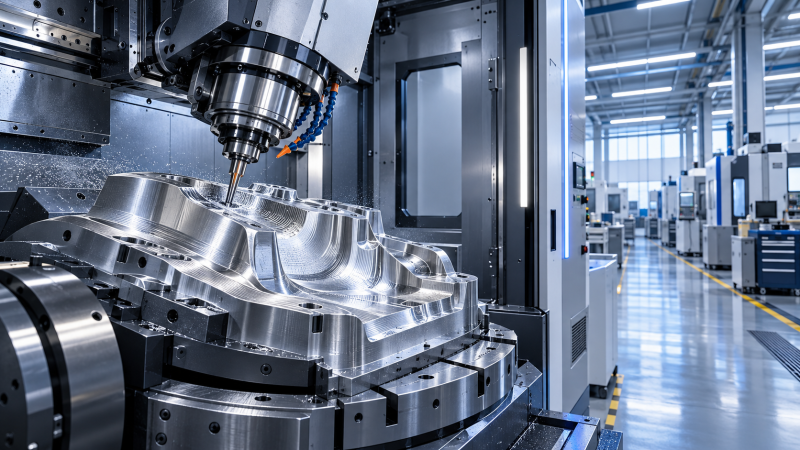
A faster CNC controller can improve machining throughput, but only when the controller is the limiting part of the process. Its most visible effect is not simply a higher spindle speed or faster axis travel. It is the controller’s ability to read program blocks, calculate motion, maintain interpolation, and issue axis commands quickly enough for the machine to follow the intended toolpath without unnecessary deceleration.
This matters most on parts containing dense 3D surfaces, short line segments, frequent contour changes, drilling patterns, or simultaneous multi-axis motion. In those programs, cnc controller cycle time speed affects how closely the machine can sustain the programmed feed rate. A machine may have capable servos, linear guides, and a high-speed spindle, yet still lose productive time if its controller cannot process the incoming toolpath fast enough.
The practical question is therefore not, “Is this controller fast?” It is, “Does controller performance reduce non-cutting motion, prevent feed-rate loss on our actual programs, and improve output without creating tolerance, tool-life, or reliability problems?”
Cycle time is the result of several systems working together
Machining cycle time is often discussed as though it were determined by feed rate alone. In production reality, it is made up of cutting time, positioning time, tool changes, probing or inspection routines, spindle acceleration, programmed dwell, and controller response during motion. A controller has a direct influence on some of these elements and an indirect influence on others.
During contour machining, the controller continuously converts programmed coordinates into synchronized axis movement. For a simple straight cut, this task is relatively light. For a complex freeform surface produced from thousands of short segments, the controller must process a far greater number of motion instructions. If it cannot calculate the next motion sequence early enough, it may slow the axes before directional changes. The programmed feed rate remains visible in the NC code, but the actual average cutting feed falls.
That distinction is important when evaluating throughput. A CAM simulation may estimate cutting time from programmed feeds and path lengths. The machine’s recorded cycle time reflects what the control, servos, axes, and spindle were actually able to execute. A recurring gap between the two is often a useful indication that the process needs closer examination.
Where controller speed has the greatest production effect
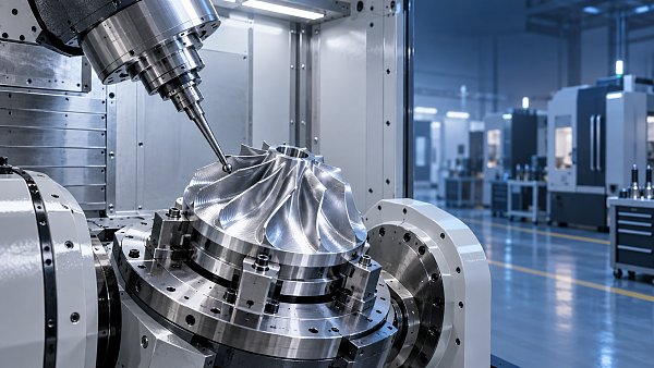
Controller processing performance is most valuable where motion is information-heavy rather than simply fast. High-speed finishing of molds, dies, impellers, blisks, medical components, and complex aerospace structures commonly involves dense toolpaths. Small radii, short chord lengths, scallop-controlled finishing, and five-axis orientation changes all increase the calculation burden.
In these applications, a control with stronger look-ahead capability can examine upcoming program blocks and prepare smoother motion through corners and curvature changes. Rather than reacting to each block only as it arrives, the controller anticipates acceleration and deceleration requirements. This can reduce feed fluctuations, improve surface consistency, and lower the time spent moving below the programmed feed rate.
The value is lower on long, uncomplicated roughing cuts where the machine can maintain a stable feed over substantial distances. A faster controller will not transform a process that is fundamentally restricted by spindle power, chip evacuation, tool engagement, or fixture rigidity. It may still improve positioning and program handling, but the expected throughput gain should be modest.
Block processing, interpolation, and look-ahead are not interchangeable
Controller specifications are often reduced to a single figure such as block-processing speed. That can be useful for comparison, but it should not be treated as a complete measure of production performance. The controller must also interpret the program format, apply acceleration limits, coordinate multiple axes, manage smoothing functions, and protect geometric accuracy.
Block processing describes how efficiently a controller handles successive program instructions. It becomes relevant when the CAM output consists of very short linear moves. A program with many tiny blocks can force an older or less capable control to pause or slow between commands, creating visible marks on finished surfaces and increasing machining time.
Interpolation performance concerns the calculation of coordinated axis movement. Circular, helical, spline-based, and multi-axis paths require the controller to generate smooth motion while keeping axes synchronized. Good interpolation helps the machine preserve surface quality and avoid abrupt velocity changes.
Look-ahead allows the control to inspect a sequence of upcoming moves. This supports smoother cornering because the controller can calculate where it must begin slowing down and where it can safely maintain momentum. Look-ahead is especially useful when the program contains continuous small direction changes rather than isolated sharp corners.
These features must be configured for the application. Excessive smoothing can alter the executed path enough to affect a tight geometric tolerance. Insufficient smoothing can preserve every programmed segment but create inefficient, jerky motion. The correct balance depends on the feature tolerance, surface requirement, tool diameter, finishing allowance, and permitted deviation from the nominal toolpath.
A controller cannot overcome machine dynamics
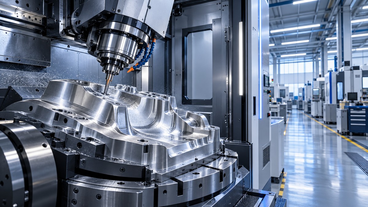
It is easy to attribute every cycle-time problem to the CNC when the machine appears to hesitate. Yet a controller can only command motion within the limits of the mechanical system. Axis acceleration, jerk limits, servo tuning, ball-screw or linear-motor condition, rotary-axis inertia, and machine structure all determine how quickly the machine can change direction while remaining stable.
A dense finishing toolpath may be slowed because the controller cannot process blocks quickly enough. It may also be slowed because the axes physically cannot accelerate and decelerate at the required frequency. These causes can produce similar symptoms, but the corrective action is different.
If the actual feed rate drops heavily even on relatively smooth paths, or if acceleration-related alarms, vibration, or following errors occur, the machine dynamics may be the primary constraint. If the feed rate falls mainly on short-segment CAM output while the machine behaves normally on arcs or longer moves, program density and controller processing are more likely contributors.
Rotary axes deserve separate attention in five-axis work. A linear toolpath may require rapid changes in rotary-axis orientation. If a rotary axis reaches its velocity or acceleration limit, the controller must reduce the entire coordinated motion. Improving linear-axis capability alone will not solve this restriction.
CAM settings can either reveal or hide controller limitations
Before specifying a new control or machine, review the CAM output. Some post-processing choices generate unnecessarily dense linearized motion. A surface that could be represented efficiently with arcs, splines, or suitable high-level motion commands may instead be exported as a very large number of short G1 blocks. The result is larger files, higher data-processing demand, and more opportunities for the machine to reduce feed.
CAM tolerance should match the functional requirement of the part. Setting an extremely fine chordal tolerance for a non-critical surface can create a program that is difficult for any machine to execute efficiently. The output may look more precise in software while providing no measurable benefit on the finished component. Conversely, loosening tolerance too far can leave faceting, blend errors, or unacceptable dimensional deviation.
Postprocessor quality also matters. The post should be matched to the controller and machine kinematics so that it uses supported interpolation, smoothing, drilling cycles, and multi-axis functions correctly. A generic post can produce safe motion but still leave cycle time and surface quality on the table.
Do not optimize only by raising feed rates
Increasing programmed feed is a common response to missed capacity targets. It works only when cutting conditions, tool engagement, machine dynamics, and controller execution all have available margin. If the control is already slowing through small segments, increasing the programmed feed may have little effect on actual material removal time. It can also make feed fluctuation more severe.
A better approach is to compare programmed feed with actual feed during representative operations. Identify where the machine loses speed, then classify the reason: controller processing, path geometry, axis limits, cutting load, or an intentional process command. This turns a broad “the cycle is too slow” complaint into a set of correctable causes.
How to assess throughput before buying or upgrading
Controller selection should be based on the parts that determine capacity, not on a demonstration program chosen for sales presentation. Use a representative group of NC files that includes the most demanding finishing path, a typical production part, and a part with high positioning or tool-change frequency. The evaluation should include the full machining sequence, not only one optimized cut.
- Break down the current cycle. Separate cutting, air cutting, indexing, tool changes, probing, and dwell. Controller improvements only address part of the total.
- Measure actual motion behavior. Review feed-rate traces, axis load, alarms, and recorded cycle times. Look for repeatable slowdowns on specific toolpath types.
- Check the CAM and postprocessor first. Confirm whether excessive segmentation, unsuitable tolerance settings, or unsupported output formats are creating avoidable demand.
- Evaluate the machine as a system. Compare controller capability with axis acceleration, rotary-axis performance, servo response, spindle behavior, and tool-change mechanics.
- Validate part quality alongside time. A shorter cycle that produces surface defects, dimensional drift, or unstable tool life is not an improvement in usable throughput.
For an upgrade decision, the most meaningful comparison is the stable cycle time achieved while meeting the required tolerance and finish. A faster result obtained only by relaxing quality controls or increasing operator intervention should not be counted as reliable capacity.
Common mistakes in interpreting CNC cycle time speed
One mistake is assuming that a high-speed controller automatically makes every operation faster. In a heavy machining cycle governed by spindle torque and chip evacuation, controller speed may have little influence. Another is looking only at rapid traverse rates. Rapid motion matters during long non-cutting moves, but it does not describe contouring behavior or the ability to sustain feed through complex geometry.
It is also risky to compare controllers by one published capability alone. Differences in look-ahead settings, smoothing modes, program format, axis tuning, and machine configuration can produce very different results from similar-looking specifications. The relevant question is whether the complete machine-control-CAM combination can execute the required part program efficiently and repeatably.
Finally, do not treat cycle-time reduction as separate from quality control. High-speed contouring can expose issues in tool balance, holder runout, vibration, thermal movement, and workholding. When the process is pushed faster, these factors become more visible rather than less important.
What to confirm before changing the control strategy
Start with the parts that create scheduling pressure or occupy the most spindle hours. Determine whether their time is spent in complex contouring, repeated positioning, tool changes, inspection cycles, or cutting limited by the material and tooling. This establishes whether controller capability is a worthwhile improvement path.
Where dense toolpaths are the issue, optimize CAM tolerance and postprocessor output before assuming hardware replacement is necessary. Where the controller remains the constraint after those checks, prioritize a solution with suitable multi-axis interpolation, effective look-ahead, compatible smoothing controls, adequate program handling, and diagnostic visibility into actual motion behavior.
The strongest throughput improvement comes from matching controller cycle-time capability to the part geometry, machine dynamics, and process standard. Faster command execution is valuable when it lets the machine cut smoothly at the rate the process can genuinely support. It is not a substitute for a stable machining system, but it can be the difference between a nominal feed rate on paper and productive spindle time on the shop floor.
Recommended News
 How CNC controller cycle time speed affects machining throughputCNC controller cycle time speed can raise machining throughput by sustaining feed rates on complex toolpaths. Learn how to optimize CAM, look-ahead, and machine dynamics.
 When a 4 axis vertical machining center is the better fit than 3-axisDiscover when a 4 axis vertical machining center outperforms 3-axis machining—reduce setups, improve datum control, and boost efficiency for complex multi-face parts.
 When industrial fasteners bolts need traceable material certificationIndustrial fasteners bolts need traceable material certification for critical applications. Learn what QA teams should verify to reduce risk and ensure compliance.
 How to size pump systems for cooling circuits for stable flow ratesPump systems for cooling circuits: learn how to match flow, total dynamic head, NPSH, and controls for reliable, energy-efficient cooling performance.
 When does software as a service reduce CNC data management costs?Software as a service can lower CNC data management costs by reducing IT overhead, manual reporting, and disconnected records. Discover when SaaS delivers measurable savings.
 CNC investment trends 2026: are automation upgrades taking priority?CNC investment trends 2026 reveal why automation upgrades are reshaping capacity plans. Compare robots, pallet systems, and new machines for smarter CNC growth.
 How to size high pressure pumps for stable chemical injection ratesHigh pressure pumps sizing guide for stable chemical injection rates—learn how to balance flow range, pressure, suction conditions, materials, and controls for reliable dosing.
 When organic chemicals are suitable feedstocks for synthetic lubricantsOrganic chemicals can unlock high-performance synthetic lubricants. Learn how purity, stability, compatibility, and supply control shape reliable industrial formulations.
 What machine tool market size reveals about capital spending cyclesMachine tool market size reveals capital spending cycles through order mix, automation, replacement demand, and capacity signals. Discover what drives smarter investment decisions.
 What causes solar inverters to trip repeatedly after installationSolar inverters tripping repeatedly? Discover key causes, from grid voltage and DC faults to wiring, settings, heat, and practical troubleshooting steps.
 How a tool life calculation chart improves cutting parameter decisionsTool life calculation chart insights help optimize cutting speed, feed, and depth for predictable tool changes, better part quality, and lower machining costs.
 What to check before choosing an industrial lubricating oils factoryIndustrial lubricating oils factory selection guide: compare quality control, formulation fit, traceability, technical support, and total cost to reduce downtime risks.
 Where machine shop digital transformation delivers the fastest paybackMachine shop digital transformation delivers faster payback by reducing downtime, setup delays, quality risks, and capacity constraints with focused, measurable workflows.
 When a semiconductor manufacturing solutions provider can shorten process ramp-upA semiconductor manufacturing solutions provider can shorten ramp-up through validated hardware, change control, field support, and resilient supply chains.
 How to evaluate CNC tooling suppliers in Europe for repeatable precisionCNC tooling Europe: learn how to evaluate suppliers for repeatable precision, stable tool life, application support, traceability, and resilient delivery.
 When does manufacturing competitiveness consulting pay off for a plant?Manufacturing competitiveness consulting pays off when plants face costly constraints, capital decisions, quality risks, or supply disruptions. Learn how to build a measurable ROI case.
 How to order acoustic ceiling tiles in bulk without overbuyingAcoustic ceiling tiles bulk buying made simple: calculate accurate quantities, control waste, secure spare stock, and plan phased deliveries to avoid costly overordering.
 Which laboratory microscopes fit routine quality inspection work?Laboratory microscopes for routine quality inspection: compare stereo, digital, compound, and measuring options to improve defect detection, documentation, and throughput.
 Can AI for multi axis machining reduce errors in complex toolpaths?AI for multi axis machining helps reduce complex toolpath errors through smarter collision detection, kinematic analysis, post validation, and machine-data insights. Learn how to improve precision.
 How seamless steel pipes are checked for wall-thickness consistencySeamlesssteelpipes wall-thickness checks explained: learn how ultrasonic scanning, calibration, and tolerance control ensure reliable, pressure-ready pipe quality.
 When a horizontal boring machine for metalworking improves large-part setupHorizontal boring machine for metalworking: learn how stable datums, rotary indexing, and rigid fixturing improve large-part accuracy and setup efficiency.




Search News
Popular Tags