
CNC Routing Plywood: Testing Tooling and Hold-Down Together
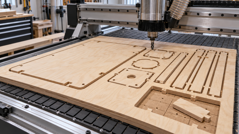
A plywood panel can produce clean edges during an initial router trial and still fail when the same toolpath reaches the last small parts in a production nest. The cutter has not necessarily changed. The remaining sheet, exposed spoilboard, vacuum leakage, and available contact area have changed around it.
That is why tooling and hold-down should be evaluated as one cutting system. A tool that controls veneer tear-out may introduce lifting forces that a particular fixture cannot resist. A cutting strategy that works on a large panel may become unreliable after surrounding material has been removed. For technical evaluators, the useful question is not simply whether a machine can route plywood, but whether it can maintain acceptable geometry, edge quality, and part retention throughout a representative nest.
Why a clean sample cut is insufficient
Plywood is a layered material rather than a uniform cutting medium. Face veneers, crossbands, adhesive interfaces, and core construction influence how an edge forms. Different plywood constructions can therefore respond differently to the same cutter. The USDA Forest Products Laboratory’s Wood Handbook describes these construction differences; they are a reason to qualify the actual purchasing specification rather than rely on a generic “plywood” sample. [1]
A useful evaluation includes the production grade, thickness range, face requirements, and likely material variation. Record visible core voids, repaired areas, panel flatness, and which face is presented upward. If an edge fails where a core void becomes exposed, changing spindle speed may not address the underlying material defect.
Part geometry matters just as much. Large cabinet sides, narrow rails, and small access covers do not present the same holding conditions. A demonstration consisting only of broad rectangles leaves unanswered questions about narrow remnants, closely spaced profiles, and the final release of small components.
Match cutter geometry to both faces and the fixture
Upcut, downcut, and compression tools offer different compromises. Their helix geometry affects chip movement and the direction of axial cutting forces. Tool selection guidance from LMT Onsrud distinguishes these configurations and their applications; the exact operating limits remain tool-specific. [2]
- Upcut tooling: Moves chips toward the spindle and can favor bottom-edge quality, but its lifting tendency must be considered when holding thin panels or small parts.
- Downcut tooling: Directs chips downward and can help protect the upper veneer. Chip clearance needs attention, particularly in deeper grooves where material cannot escape freely.
- Compression tooling: Combines opposing helix sections to support both faces under suitable engagement conditions. Its performance depends on where the transition between those sections sits relative to the panel surfaces.
A compression cutter should not be treated as an automatic cure for tear-out. If a shallow first pass leaves the upcut section cutting the upper face, the intended top-edge benefit may not be achieved. Entry strategy, cutting depth, and the tool’s specified upcut length need to be considered together.
Also record cutting diameter, flute count, cutting length, projection from the collet, and tool condition. Excessive projection introduces another possible source of deflection. A comparison between cutters becomes difficult to interpret if projection, collet condition, or tool wear changes without being documented.
For initial settings, use the selected cutter manufacturer’s recommendations. The basic relationship is chip load per tooth = feed rate ÷ (spindle speed × flute count), using consistent units. This describes nominal chip load, not a complete prediction of cutting behavior. Machine acceleration, cornering, engagement, and toolpath changes affect what happens locally. [2]
Assess vacuum performance at the workpiece
The basic pressure-force relationship is straightforward: pressure difference multiplied by effective sealed area gives an idealized normal holding force. Actual resistance to sliding or lifting also depends on leakage, contact conditions, panel stiffness, and cutting loads. Pump capacity alone does not establish the holding margin for a finished part.
With a porous spoilboard, air must pass through the board while unnecessary leakage is controlled. Surface condition, exposed table area, zoning, and perimeter sealing can all affect the result. A bowed panel may also behave differently from a flat qualification sample because the initial contact conditions differ.
Record where vacuum is measured and at which stage of the cut. A reading near the pump is not automatically equivalent to conditions at every part. Comparing readings before cutting, during progressive sheet separation, and near the end of the nest is more informative than recording one idle value.
Small components deserve separate attention. Once isolated, they have less effective holding area and may rotate under cutting loads even when the overall sheet initially appeared secure. Tabs or an onion-skin strategy can preserve connections, but they introduce trade-offs: tab removal requires finishing, while an onion skin must be consistent enough to remain intact until its planned removal.
Build a trial that exposes tooling–fixture interactions
Define acceptance criteria before the trial. Otherwise, a visually attractive edge can distract from dimensional errors, excessive finishing, or unreliable part retention. Criteria should come from the drawing and downstream process: an edge intended for banding may have different requirements from an exposed furniture edge.
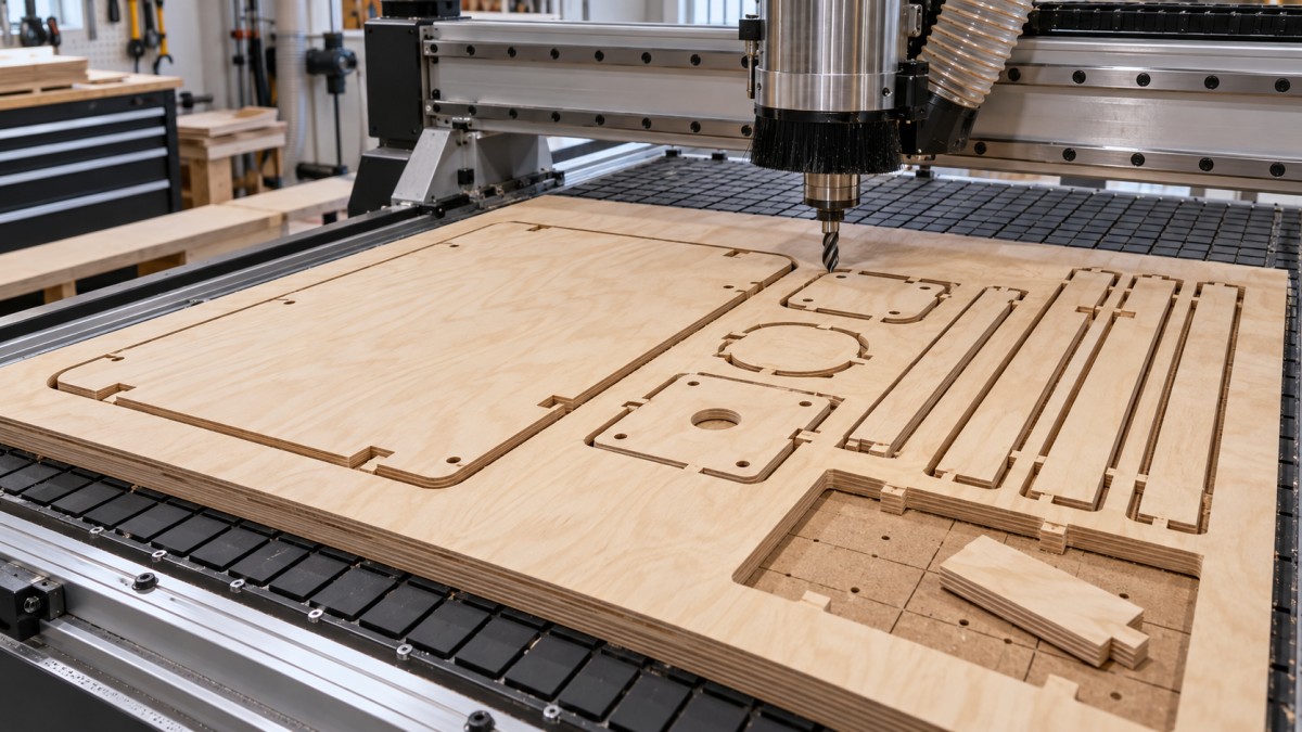
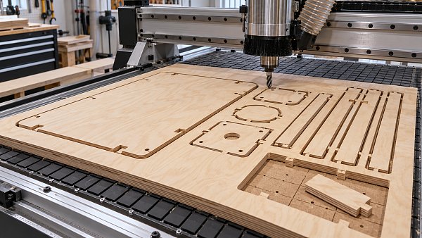
Use a representative nest containing broad parts, narrow strips, internal features, and the smallest routinely produced components. Include different cutting directions relative to the face veneer. Preserve enough access for inspection without replacing the production layout with an unusually easy demonstration.
A staged trial helps separate causes without losing sight of their interaction:
- Establish a baseline. Use documented material, a serviceable spoilboard, known tooling, and the supplier’s recommended starting conditions. Record the complete toolpath and holding arrangement.
- Compare tooling under unchanged holding conditions. Inspect both faces, dimensions, chip evacuation, and behavior at entries, corners, and exits.
- Compare holding strategies with the preferred tool. Evaluate production-relevant zoning, masking, tabs, or onion-skin arrangements without deliberately creating an unsecured setup.
- Repeat the complete nest. Confirm that the selected combination works as surrounding material disappears, not merely on an isolated coupon.
Keep other variables stable during each comparison. Changing cutter geometry, feed rate, cutting depth, vacuum zoning, and cut order simultaneously may produce a successful part, but it will not reveal which change mattered. Once individual effects are understood, test the combined production recipe.
Repeatability also requires a record of tool use. Comparing a fresh cutter with one that has already processed substantial material confounds geometry with wear. If purchasing specifications permit different plywood constructions or suppliers, include that variation in qualification rather than assuming equivalent machining behavior.
Interpret defects before adjusting the process
Similar-looking defects can have different causes. Inspect the location and timing of damage, not just its appearance after unloading.
Reducing feed rate is not a universal correction. At unchanged spindle speed, it reduces nominal chip load and may increase rubbing rather than resolve the cause. Increasing vacuum may help a retention problem but cannot correct inappropriate cutter engagement. Adjustments should follow a plausible diagnosis and a controlled comparison.
Inspect both faces before sanding or edge finishing conceals evidence. Dimensional checks should include features cut early and late in the nest. Internal features cut while the panel remains continuous can be compared with outer profiles completed after separation to help identify whether movement develops during release.
Turn machine evaluation into a documented capability test
When assessing ZD1325 plywood routing capabilities, use the product information as a starting point for defining the demonstration, not as a substitute for machining evidence. The relevant question is whether the proposed configuration can process the evaluator’s plywood, tooling, and part mix under agreed acceptance conditions. No particular spindle, vacuum arrangement, tolerance, or output rate should be assumed without confirmation.
Request a record of the demonstrated configuration: spindle and toolholder arrangement, cutter identification, vacuum equipment, active zones, spoilboard preparation, extraction setup, and CAM strategy. Distinguish equipment included in the quotation from demonstration accessories. A result obtained with additional fixturing needs that fixturing included in the production plan and cost comparison.
Measure elapsed production time rather than cutting time alone. Loading, vacuum establishment, tab removal, edge cleanup, unloading, and spoilboard maintenance all affect practical throughput. A faster toolpath may have little value if it creates rework or requires operators to separate and finish every component manually.
Evaluate the routine maintenance state as well as the freshly prepared condition. Ask how spoilboard resurfacing, sealing checks, cutter replacement, and collet inspection will be controlled. Acceptance should describe a repeatable process window, not an exceptional demonstration requiring undocumented operator intervention.
Keep retention tests within a defined safety procedure
Do not investigate marginal holding by continuing to cut a visibly moving part. Define stop conditions before testing and use the machine manufacturer’s operating procedures, guarding provisions, and workholding instructions. A process that depends on someone manually restraining material during cutting is not an acceptable demonstration method.
For United States operations, OSHA’s general machine-guarding requirements address hazards including rotating parts and flying chips. Its hazardous-energy standard applies to covered servicing and maintenance activities. These are separate obligations; a successful routing trial does not establish machine safety or regulatory compliance. Applicable local requirements and a site-specific assessment still need attention. [3]
The purchasing decision should rest on the combination that remains stable through the whole nest: suitable cutter engagement, controlled leakage, credible part retention, and acceptable finished geometry. If the result depends on a particular cut sequence, retention method, or spoilboard condition, document that dependency as part of the qualified process.
Technical references
[1] USDA Forest Products Laboratory. Wood Handbook—Wood as an Engineering Material. General Technical Report FPL-GTR-282, 2021. Chapter 11, “Wood-Based Composite Materials,” provides background on plywood construction.
[2] LMT Onsrud. CNC Production Routing Guide, tool-selection and chip-load guidance. Use the current recommendations for the specific cutter when establishing cutting parameters.
[3] Occupational Safety and Health Administration. 29 CFR 1910.212, “General requirements for all machines”; and 29 CFR 1910.147, “The control of hazardous energy (lockout/tagout).”
Recommended News
 Can lean manufacturing reduce changeover time in injection molding?Discover how lean manufacturing can reduce injection molding changeover time with SMED, better preparation, standardized processes, and quality controls.
 How to estimate the payback period for a CNC machining centerEstimate your CNC machining center investment payback with a practical formula, installed cost checklist, cash-flow examples, and risk analysis.
 How cloud computing supports remote CNC machine monitoringDiscover how cloud computing enables remote CNC machine monitoring, from real-time alerts and troubleshooting to secure integration and smarter pilot decisions.
 LANXESS and BPCL to Explore Immersion Cooling Fluids and Advanced LubricantsLANXESS and BPCL are exploring immersion cooling fluids and advanced lubricants. Discover what the proposed collaboration could mean for buyers and suppliers.
 What OEM manufacturing support is needed for smart actuator testing?Explore OEM manufacturing support for smart devices: precision fixtures, firmware access, load testing, and traceable results. Learn what to demand for reliable smart actuator validation.
 How minimum order quantities affect wholesale bedding set costsBuying bedding sets wholesale? Discover how minimum order quantities affect unit prices, inventory risks, and total costs—and learn to negotiate smarter deals.
 What should mechanical seal technical specification documents include?Explore technical specification support documentation for mechanical seals, covering materials, drawings, standards, and testing to reduce risks and make confident supplier approval decisions.
 Shanghai Plan Targets Ultra-Precision Machining and Five-Axis Machine Tool UpgradesShanghai's ultra-precision machining and five-axis machine tool upgrade priorities could shape equipment investment. Explore potential opportunities and what buyers should verify.
 How global trade tariffs affect the landed cost of injection moldsDiscover how global trade tariffs affect injection mold landed costs. Compare duties, freight, and customs rules to avoid hidden expenses and make smarter sourcing decisions.
 How to qualify a catalyst manufacturer for synthetic oil productionQualify a catalysts manufacturer for synthetic oil production with practical checks for performance, batch quality, and scale-up. Learn how to reduce risk and select a reliable supplier.
 Are CNC spindle suppliers expanding local repair for five-axis machines?Explore cnc spindle supplier trends in local repair for five-axis machines. Learn how to verify repair capacity, compare exchange options, and choose support that reduces downtime.
 China’s Base Oil Imports Hit 2026 Low in September; Top Three Suppliers Account for 82.5%China’s base oil imports hit a 2026 low of 67,400 tonnes in September, with three origins accounting for 82.5%. Explore the data and implications for sourcing and supply risk.
 How to verify batch quality with an industrial lubricating oils exporterBuying from an industrial lubricating oils exporter? Learn how to verify batch test results, sampling, and traceability to reduce purchasing risks and protect equipment.
 How to set relubrication intervals for industrial maintenanceImprove industrial maintenance with smarter relubrication intervals. Learn how to balance bearing conditions, grease quantity, and monitoring to reduce downtime and avoid costly failures.
 How to spot misleading claims on eco-friendly baby productsShopping for ecofriendlybabyproducts? Learn to spot greenwashing, verify certifications, and assess material and disposal claims so you can choose with confidence.
 John Crane Signs Three-Year Agreement to Improve Phosphate Mine Seal ReliabilityJohn Crane's three-year agreement targets phosphate mine seal reliability with on-site expertise and mechanical seal solutions. Explore its potential to reduce downtime.
 CNC Routing Plywood: Testing Tooling and Hold-Down TogetherExplore ZD1325 plywood routing capabilities by testing tooling and hold-down together. Learn how to assess edge quality, part retention, and repeatability before you invest.
 Which CNC Machine Accuracy Metrics Matter Most for Tight Tolerances?How often should CNC cutting tools be replaced in production? Discover key accuracy metrics, wear signals, and thermal controls to hold tight tolerances and reduce costly scrap.
 How Often Should CNC Cutting Tools Be Replaced in Production?What is the difference between precision tooling and standard tooling? Learn when to replace CNC cutting tools using wear limits and quality checks to reduce downtime and protect part quality.
 What Is the Difference Between Precision Tooling and Standard Tooling?When is die casting cheaper than CNC machining? Compare precision and standard tooling, uncover cost drivers, and learn how to choose the right process for reliable parts at lower total cost.
 Which Die Casting Defects Should You Check Before Supplier Approval?What die casting defects should be checked before supplier approval? Explore key defects, inspection methods, and acceptance limits to qualify suppliers confidently and reduce costly failures.














Search News
Popular Tags