
What Causes Pressure Fluctuations in an Industrial Pump?
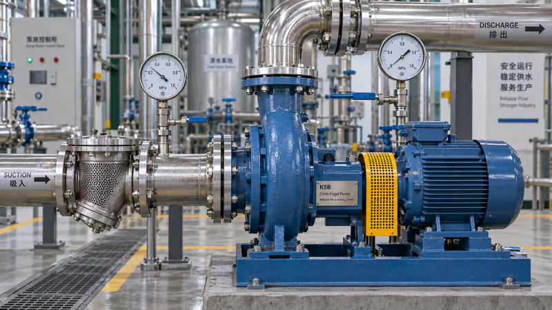
Pressure fluctuations in an industrial pump usually come from unstable suction conditions, entrained air, changing process demand, control-loop hunting, or hydraulic and mechanical deterioration. Positive-displacement pumps also produce inherent pulsation. When a discharge gauge swings during production, the immediate question is whether it reflects expected operation, a measurement problem, or an instability that could damage the pump or disrupt the process.
Start by comparing suction pressure, discharge pressure, flow, actual pump speed, and valve position on the same timeline. A pressure change following a valve movement points toward the system; fluctuations accompanied by falling suction pressure suggest an inlet restriction or inadequate suction head. Noise, vibration, temperature, and the timing of the disturbance help narrow the cause before settings or components are changed.
Is the pressure fluctuation real, or is the instrument misleading?
A vibrating gauge pointer does not necessarily mean the whole process is experiencing the same pressure swing. Mechanical vibration, a damaged gauge, a blocked pressure connection, or an unsuitable transmitter configuration can distort the reading. Conversely, heavy damping can hide short pressure spikes that still affect piping and seals.
Compare the installed instrument with a verified reference at a suitable pressure connection. Check its range, calibration status, response time, and connection condition. Long impulse lines, trapped gas in liquid-filled lines, or accumulated solids can delay or alter the indicated pressure.
Measurement location matters. A sensor near a reciprocating pump discharge may detect strong local pulsation, while a downstream sensor records a smoother signal. A reading after a regulating valve cannot be treated as pump discharge pressure without accounting for the intervening pressure loss.
Record both the size and timing of the fluctuation. Slow, repeating swings often suggest changing demand or control hunting. Rapid pulses may relate to displacement cycles or hydraulic excitation. Sudden spikes following valve closure suggest a transient event. Ordinary control-system logging may be too slow to capture rapid pulsation.
Could the pump be starved at the suction inlet?
Inadequate suction conditions are a frequent cause of unstable delivery. A falling supply-tank level, fouled strainer, partially closed valve, undersized suction pipe, or increased liquid temperature can reduce the pressure available at the pump inlet. Higher flow increases suction-line friction losses, so a pump that runs acceptably at one duty may become unstable at another.
Cavitation occurs when local pressure falls below the liquid’s vapor pressure and vapor bubbles form, then collapse as pressure recovers. It can cause crackling or gravel-like noise, increased vibration, fluctuating head, and eventual surface damage. Noise alone is not conclusive because entrained gas and mechanical faults can sound similar.
Evaluate net positive suction head available, or NPSHA, using actual operating conditions. Include source pressure, liquid level, temperature-dependent vapor pressure, elevation, and suction losses. Compare it with the manufacturer’s NPSH requirement and the appropriate application margin. Published NPSHR is not a guarantee of cavitation-free operation at that value.
- Check whether fluctuations become worse as the supply level falls or liquid temperature rises.
- Measure the differential pressure across suction strainers or filters rather than judging their condition from appearance.
- Confirm suction valves are in their intended operating position and the source tank is properly vented or pressurized.
- Review recent changes in flow demand, fluid viscosity, or suction-pipe configuration.
Do not throttle the suction valve to stabilize pressure. For a centrifugal pump, reducing speed or flow may temporarily improve suction conditions, but only within approved operating limits. Persistent cavitation calls for correcting the inlet conditions rather than masking the discharge signal.
How do air entry and cavitation differ?
Air entrainment introduces noncondensable gas; cavitation creates vapor from the pumped liquid. Both can interrupt hydraulic continuity, but their remedies differ. Air may enter through leaking suction joints operating below atmospheric pressure, vortexing at a tank outlet, inadequate submergence, or aerated return flow.
A suction connection can admit air without leaking liquid outward. This makes a dry exterior a poor test of suction integrity. Inspect joints, gaskets, seal arrangements, and priming connections using procedures suitable for the fluid and equipment.
Look for froth in the source vessel, recurring loss of prime, and fluctuations linked to low tank level or return-flow activity. In positive-displacement pumps, gas compression can delay pressure development and make delivery erratic. In centrifugal pumps, excessive gas can reduce head or cause loss of pumping.
Correct the entry path, improve outlet submergence, or separate aerated return flow from the suction pickup. Venting trapped gas may restore operation, but repeated venting is not a substitute for eliminating the source. Never open a vent or connection on a pressurized, hot, or hazardous-fluid system without the prescribed isolation procedure.
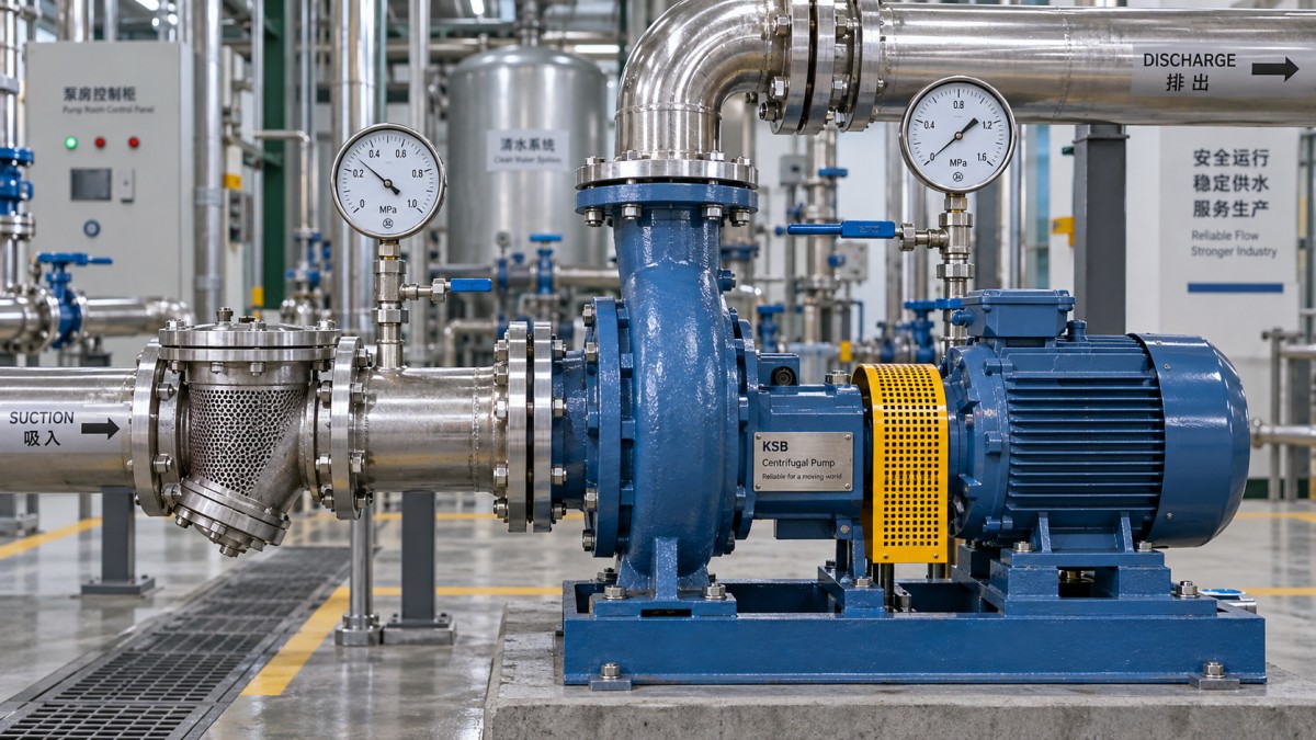
Use the pressure pattern to locate the disturbance
The relationship between signals is usually more useful than the discharge pressure alone. These patterns guide investigation; none proves a diagnosis without operating data.
Can process demand change pressure without a pump fault?
Yes. A pump operates within a connected hydraulic system. Opening another process branch, cycling a spray manifold, changing a filter’s resistance, or moving a control valve changes that system’s demand. A fixed-speed centrifugal pump then moves to a different point on its pump curve, altering flow and head.
Check production events against the pressure trend before dismantling the pump. Parallel pumps starting and stopping can also shift the operating point. Poor sequencing or unstable check-valve behavior may create repeated disturbances even when each pump is mechanically sound.
Compare differential pressure across the pump, not just discharge gauge pressure. For a fuller assessment of developed head, account for fluid density and relevant elevation and velocity differences. A changing suction pressure can move the discharge reading without an equivalent change in pump-developed head.
Operation far from a centrifugal pump’s preferred operating region can introduce recirculation, vibration, and unstable hydraulic behavior. Check the actual duty against the manufacturer’s curve and allowable operating range. A minimum-flow return should be assessed for capacity and function, not simply assumed effective because it is installed.
Why does a variable-speed pump keep hunting around its setpoint?
A pressure controller may repeatedly accelerate and decelerate the pump when its response is too aggressive for the system delay. Pressure rises above the target, the controller reduces speed, pressure falls, and the cycle repeats. Poor sensor placement, noisy feedback, excessive filtering, or changing process volume can contribute.
Trend the pressure setpoint, measured pressure, controller output, actual speed, and any active regulating-valve position together. Two controllers acting on the same pressure variable—for example, a speed controller and a downstream valve controller—may oppose one another unless their roles are coordinated.
Before retuning, verify sensor accuracy and actuator behavior. A sticking valve can create a limit cycle that resembles poor PID tuning. Speed limits, minimum-flow protection, and start-stop logic can also force oscillation. Controller changes should follow the site’s change procedure, with process protection retained and performance checked under representative demand conditions.
When is pulsation normal for a positive-displacement pump?
Reciprocating diaphragm and plunger pumps deliver flow in cycles, so some pulsation is inherent. Gear, screw, and other rotary designs can also produce periodic ripple. Whether it is acceptable depends on the pump design, piping response, process tolerance, and component pressure limits; there is no universal acceptable percentage.
A new increase in pulsation warrants investigation. Suction starvation, gas pockets, worn or sticking pumping valves, and an ineffective pulsation dampener can amplify the normal waveform. Check dampener sizing, location, compatibility, and precharge against manufacturer instructions. Isolate and depressurize it before service; do not adjust precharge by guesswork.
Do not throttle or close a positive-displacement pump’s discharge as a diagnostic experiment. It can rapidly generate excessive pressure. Confirm that correctly rated overpressure protection is installed and functional. A relief valve repeatedly opening and reseating may itself produce oscillation, but changing its setting without verifying system limits is unsafe.
Could wear, alignment, or a check valve cause the fluctuation?
Internal wear often first appears as reduced efficiency or inability to achieve the former duty. Increased clearances, damaged impellers, and worn pumping valves can also contribute to unstable performance. Compare current flow, differential pressure, speed, and power with previous records at similar fluid conditions.
Misalignment, bearing damage, looseness, and pipe strain generally require vibration and mechanical checks rather than pressure-based diagnosis alone. Pressure fluctuation accompanied by a changed vibration signature, abnormal bearing temperature, or seal leakage justifies a controlled shutdown and inspection.
Check valves deserve separate attention when disturbances coincide with pump switching or rapid flow changes. Chattering can occur when flow is insufficient to hold a valve steadily open, while delayed closure can permit reverse flow and a pressure surge. Valve selection should reflect actual flow and transient behavior, not pipe size alone.
What should be checked first during troubleshooting?
- Establish safe operating limits. Check pressure excursions against equipment ratings and site alarm limits. Escalate severe vibration, loss of prime, leakage, or damaging transients under the plant’s shutdown procedure.
- Verify the measurement. Confirm instrument condition and location. Use an appropriate recording rate for the suspected disturbance.
- Capture correlated data. Record suction and discharge pressure, flow, speed, tank level, temperature, valve position, and pump-switching events on a shared timeline.
- Inspect external causes first. Investigate supply restrictions, gas entry, process switching, and control behavior before assuming internal damage.
- Test one change at a time. Make authorized adjustments within operating limits, then compare the same signals under similar demand.
- Validate across the operating range. A steady gauge at one condition does not prove resolution. Check low-demand operation, peak demand, and relevant switching events without bypassing safeguards.
Replacement becomes a reasonable option when verified duty conditions fall outside the installed pump’s suitable range, or inspection confirms damage that cannot be economically repaired. Specify the required flow and head range, fluid properties, suction conditions, control arrangement, and acceptable pulsation—not just the previous pump’s model or motor power. Otherwise, a new unit may reproduce the same pressure instability.
Recommended News
 How to calculate payload for industrial robots removing molded partsSize industrial robots for molded-part removal with confidence. Learn to calculate total payload, center of gravity, inertia, and extraction loads to avoid overloads and optimize cycle times.
 When do automated CNC cell systems pay off for 5-axis machining?When do automated cnc cell systems pay off for 5-axis machining? Discover how demand, unattended reliability, and total costs shape ROI—and build a stronger investment case.
 When is industrial procurement support worth the cost for tooling?When is industrial procurement support worth the cost for tooling? Discover how to compare total costs, assess supplier risk, and build a clear break-even case before you invest.
 How to assess a mold manufacturer's cooling design expertiseAssess a mold engineering manufacturer's cooling expertise with key checks for thermal simulations, circuit flow, and mold trials. Learn what evidence to demand before approving your supplier.
 How to vet OEM mold suppliers in a manufacturing directoryUsing a manufacturing directory with OEM suppliers? Learn how to vet mold makers, verify capabilities, compare quotes, and define acceptance criteria to reduce sourcing risk.
 Desma USA Introduces DataHub and Molding Technology to Improve Production EfficiencyExplore Desma USA’s DataHub, valve-gate and cavity-pressure technology to see how these innovations could enhance process control and improve molding production efficiency.
 How energy costs shape manufacturing competitiveness in the Middle EastManufacturing competitiveness Middle East guide: discover how energy costs, efficiency, and reliable power shape factory margins—and make smarter site and equipment investments.
 Choosing a compatible automatic tool changer for 5-axis CNCs in EuropeAutomatic tool changer Europe guide: find the right fit for your 5-axis CNC. Compare tool limits, collision clearance, safety and local support to avoid costly mistakes.
 When is a Swiss-type lathe worth the investment in Europe?Swiss type lathe Europe: is it worth the investment? Compare ownership costs, verified savings and payback scenarios to build a stronger business case before you buy.
 Will wireless alarm systems still work during a power outage?Will wirelessalarmsystems work during a power outage? Discover which features stay active, why cellular backup matters, and what to check before choosing your alarm.
 What affects lead times when buying carbide inserts in Europe?Buying carbide inserts Europe-wide? Discover how stock, specifications, factory schedules and shipping affect lead times, and learn what to confirm to keep production running.
 Which window treatments provide privacy without blocking daylight?Discover window treatments that balance privacy and daylight. Compare cellular shades, sheers, and layered options to find the right fit—and avoid nighttime privacy surprises.
 How to verify a 5-axis CNC machine supplier's MTTF claimsVerify MTTF for CNC machine tools supplier claims with expert checks on failure records, operating hours, and confidence bounds. Make a smarter 5-axis CNC investment.
 How to choose STEM education kits for small-group classroom workChoose STEM education kits that keep every student engaged. Discover how to assess group participation, lesson fit, safety, and long-term costs to make smarter classroom purchases.
 How to read an EDM surface finish Ra chart in µm and µinRead an EDM surface finish Ra chart with confidence. Learn µm-to-µin conversions, avoid costly unit errors, and choose finish targets backed by reliable inspection.
 How to use data analytics to reduce scrap in injection moldingUse data analytics to reduce injection molding scrap. Learn which production data to track, how to uncover defect causes, and how to verify improvements that cut waste and protect quality.
 What affects the cost of axis calibration on a 5-axis machine?Understand axis calibration cost for 5-axis machines, from rotary-axis condition to downtime. Learn how to compare quotes, avoid hidden fees, and secure verified accuracy.
 How to verify a supplier's chip removal rate measurement accuracyReview chip removal metrics supplier teams provide. Learn how to verify removal rates, calibration, timing, and uncertainty for smarter, more confident purchasing decisions.
 How cryogenic service requirements affect fluid control system pricesExplore fluid control systems price drivers for cryogenic service, from materials and testing to insulation. Learn how to compare quotes, avoid hidden costs, and buy with confidence.
 When is die-cast aluminum suitable for lightweight vehicle housings?Light-weighting vehicle materials: Discover when die-cast aluminum suits vehicle housings, balancing weight savings, tooling costs, sealing, and durability for smarter design decisions.
 How to specify CNC machining tolerances for press-fit assembliesSpecify CNC machining tolerance for reliable press-fit assemblies. Learn to calculate interference, control thermal effects, and verify supplier capability to prevent costly fit failures.




Search News
Popular Tags